How Floating Mount Prevents Separable Connector Overheating & Failure
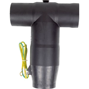
What causes a separable connector to overheat even when torque specs are met? Misalignment — when the plug and receptacle deviate from coaxial alignment, contact resistance rises and localized heating begins. Floating mount technology solves this by allowing the receptacle to move radially and axially within a controlled clearance, automatically compensating for installation errors so the separable connector mates precisely under real-world conditions.
What Goes Wrong When a Separable Connector Misaligns
Field installations rarely match lab precision. Common deviation sources include:
-
Panel drilling tolerances that accumulate across multiple mounting points
-
Thermal cycles that expand and contract components at different rates
-
Cable weight imposing side load on the receptacle
-
Equipment vibration shifting mounting panels over time
The consequences follow a clear chain:
-
Contact area between mating halves decreases
-
Contact resistance rises as current paths narrow
-
Joule heating increases, driving localized temperature above rated limits
-
Sustained overheating degrades insulation and accelerates partial discharge
-
Severe cases lead to dielectric breakdown and unplanned outage
How Floating Mount Technology Compensates for Installation Tolerances
Mechanical Components That Enable Float
The socket housing is not rigidly bolted to the panel. Instead, it is suspended using components that permit controlled movement:
-
Floating eyelets — oversized clearance holes allow the socket to shift laterally on the mounting plate
-
Compression springs — provide restoring force to return the socket to neutral when unmated
-
Tapered lead-in chamfers — engage first during insertion, translating axial force into lateral motion that guides the floating receptacle into coaxial alignment
-
Sliding metallic screen — maintains shielding continuity in screened separable connectors even when the housing moves
Self-Alignment Sequence
The alignment process is fully automatic:
-
The plug enters the socket opening and contacts the lead-in chamfer
-
The chamfer converts insertion force into a lateral component, pushing the floating receptacle sideways
-
The receptacle moves until the primary contacts are perfectly coaxial; springs hold this position under slight compression
This mechanism proves effective for separable insulated connectors where operator access is restricted and blind mating is required.
Float Parameters — What the Numbers Mean
Floating systems compensate for three types of misalignment: radial offset (lateral displacement), angular misalignment (tilt), and axial tolerance (depth variation).
| Parameter | Typical Range | Function |
|---|---|---|
| Radial displacement | 0.5 – 1.0 mm | Corrects panel drilling or mounting errors |
| Angular correction | Up to 4 degrees | Compensates for skewed cable entry angles |
| Axial tolerance | 1.0 – 2.0 mm | Absorbs thermal expansion of mounting plates |
Spring rate calibration is a balancing act. Too high, and the socket cannot move freely enough to correct misalignment. Too low, and the socket may drift under vibration, leading to fretting corrosion on the separable front screened connector interface.
Industry Standards That Govern Performance
IEEE 386-2025 establishes definitions, service conditions, ratings, interchangeable construction features, and tests for shielded separable insulated connectors used on power distribution systems rated 2.5 kV through 35 kV and 900 A or less. IEC 60502-4 specifies type testing requirements for separable connectors with rated voltages from 3.6/6 kV up to 18/30 kV. IEEE 1215 provides application and operation guidance for separable connectors rated 601 V and above. Floating mount designs must meet the separating force requirements defined in these standards.
Selection Guide — Matching Float Range to Your Application
-
Verify panel flatness — panel warpage must not exceed the available radial float
-
Check cable specifications — insulation outer diameter is a key parameter for separable cable connector reliability
-
Match equipment bushing interface — IEEE 386 defines multiple interface configurations; select the type compatible with your switchgear
-
Confirm current and voltage ratings — common ratings include 200 A, 600 A, and 900 A across 15 kV to 35 kV classes
Installation Practices That Preserve Floating Function
-
Tighten mounting screws alternately in a star pattern to prevent the floating sleeve from binding in its clearance hole
-
Verify springs are not coil-bound after tightening — full compression eliminates floating action and transfers all forces to the insulating body
-
Do not apply lubricant to threaded components — this interferes with achieving correct torque values
-
Use alignment inserts for multi-pin designs to reduce the float required for secondary circuits
-
Secure cables with clamps — never let cable weight bear on the separable connector or equipment bushing
Maintenance — The “Wiggle Test” and What It Tells You
During routine inspection, manually move the socket to the extremes of its float range. If resistance is felt, clean the eyelet and sliding surfaces, then apply a thin layer of dielectric grease. Replace springs showing permanent set or deformation. A seized floating mount is a primary cause of contact overheating in screened separable connectors.
Next Step — Applying Floating Mount to Your Design
Floating mount technology converts a rigid connection into a forgiving one that adapts to real-world installation conditions. This approach guarantees consistent electrical performance, reduces mechanical wear, and extends service life. For specific clearance calculations based on your panel thickness and cable specifications, refer to the technical specification sheet for your connector system.