Safety Protocols For Cold Shrink Cable Accessories Installation
Operating in high-voltage environments demands more than just basic knowledge; it requires a systematic approach to component integration. While cold shrink cable accessories are valued for their tool-free application, their reliability depends on strict adherence to mechanical clearances and surface preparation. Failure to manage these variables often leads to catastrophic insulation breakdown during peak thermal cycles.
Pre-Installation: Identifying Potential Failure Points
Precision starts before the core is even pulled. A common mistake in the field is neglecting the compatibility between the cable diameter and the accessory range. Technicians must verify that the cable jacket is free from deep gouges, as any surface irregularity can compromise the moisture-tight seal of the cold shrink cable joint.
-
Use a calibrated caliper to confirm the cable fits the specific range of the accessory.
-
Degrease the insulation using only residue-free solvents to prevent carbon tracking.
-
Inspect the silicone body for any micro-tears that could expand during deployment.
-
Ensure all semiconducting layers are trimmed to the exact dimensions specified in the technical data sheet.
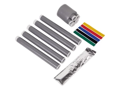
Deploying the Cold shrink joint in Confined Spaces
The primary advantage of a cold shrink joint is its ability to be installed in tight manholes or cable trays where heat torches are prohibited. To achieve a perfect interface pressure, the internal support core must be removed at a consistent speed. This ensures the elastic memory of the material exerts uniform radial pressure, effectively eliminating air pockets that could cause partial discharge.
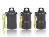
Decommissioning Safety with a Cable abandonment kit
When managing temporary power circuits or site upgrades, an energized cable left improperly terminated is a severe liability. Integrating a cable abandonment kit provides a temporary or permanent environmental seal that surpasses traditional taping methods. This process is essential for preventing water ingress from migrating into the main switchgear through the cable core.
-
Position the heavy-duty end cap at least 50mm over the cable jacket.
-
Begin pulling the rip-cord while holding the cap steady against the cable end.
-
Observe the displacement of the internal mastic seal as the cap collapses.
-
Secure any integrated grounding braids to the local earth bar using mechanical lugs.
-
Label the abandoned end with the circuit ID and date of isolation for future audit.
Performance Monitoring and Risk Mitigation
Long-term safety is confirmed through post-installation testing. Utilizing Very Low Frequency (VLF) testing at 0.1Hz allows technicians to verify the dielectric strength of the newly installed cold shrink cable accessories without damaging the existing insulation. This data-driven approach transforms a standard installation into a documented, high-reliability electrical asset.