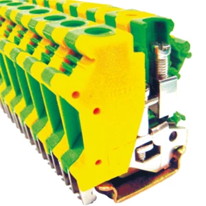
Grounding Terminal Blocks Selection Guide: Ratings, Mounting & Safety
A grounding terminal block is a modular connector mounted on a 35 mm DIN rail that terminates protective conductors (green-yellow wires) and establishes a low‑impedance fault current path to earth. When leakage or surge occurs, the block’s metal clamping foot bonds the conductor to the rail, allowing fault energy to dissipate within milliseconds—triggering the overcurrent protection device and keeping enclosure surfaces at ground potential.
What Happens When the Grounding Path Fails
Without a dedicated grounding terminal blocks, protective conductors may terminate at random points—on the chassis, through daisy‑chained wires, or directly on the rail. A phase‑to‑ground fault then faces unpredictable impedance. Fault current struggles to return to earth, and the cabinet door can rise to hazardous voltage. A technician touching it becomes the path of least resistance.
With a properly installed earth terminal block, every green‑yellow wire terminates at a single verified point. The block’s metal foot bonds to the DIN rail, which acts as an equipotential busbar. Fault current flows through the lowest impedance to the main earthing point, keeping the door at ground potential and protecting personnel.
Grounding Terminal Blocks vs Ground Bars
Panel designers often choose between ground bars and DIN rail ground terminals. The decision depends on current rating, maintenance, and layout.
Ground bars are copper or tinned bars with holes for ring lugs, mounted on standoffs. They serve as the main equipment grounding electrode, handling up to the panel’s feeder rating (65 A, 100 A, or higher). Best for VFD protective conductors, motor shields, and sub‑panel bonding.
DIN rail ground terminal blocks are modular components with metal feet that scrape the rail and clamp conductors via screws or springs. Typical ratings are 6 mm² at 57 A. Ideal for low‑current control circuits—24 VDC references, signal shield drains, and solenoid commons.
| Feature | Ground Bar | DIN Rail Terminal |
|---|---|---|
| Primary role | Central grounding point | Distributed grounding |
| Current capacity | Up to feeder rating | Usually 6 mm² / 57 A |
| Mounting | Standoffs / brackets | Snap‑on to TS‑35 rail |
| Best use | VFDs, motors, heavy feeders | Control signals, drains, commons |
Specifications for DIN Rail Ground Terminal Blocks
IEC 60947‑7‑2 governs protective conductor terminals. Selection hinges on three parameters.
Conductor cross‑section. Terminals typically accept 0.2 mm² to 10 mm². A 6 mm² terminal rated 57 A suits most industrial controls. The rating must match the largest protective conductor specified by the upstream overcurrent device.
Mounting. Most panels use 35 mm DIN rails (TS‑35 profile). The terminal snaps on via a metal clamping foot that creates the electrical bond to the rail—this bond must withstand fault currents without overheating.
Material. Insulation is polyamide with UL94 V‑0 flammability. The green‑yellow colour identifies the terminal exclusively for protective conductor use.
Connection Technologies Compared
Three common clamp types exist.
Screw terminals offer high clamping force and accept solid or stranded wires. Torque for M4 screws is typically 1.2 N·m. Over‑tightening strips threads; under‑tightening creates resistance.
Spring terminals maintain constant pressure despite thermal cycling and allow tool‑free insertion. Push‑in terminals accept solid conductors directly (stranded with ferrules). Choose screw for frequent field re‑wiring; choose spring or push‑in for high‑vibration environments.
Installation Practices That Preserve Safety
Torque control is essential. Use a torque screwdriver set to the manufacturer’s value (e.g., 1.2 N·m for M4). Strip insulation to the specified length—typically 10 mm for 6 mm² terminals. Insert the bare conductor fully; no insulation inside the clamp.
Never daisy‑chain protective conductors. Each wire must terminate at its own clamping point on the ground block terminal. Daisy‑chaining breaks single‑point grounding and adds series impedance.
Verify the connection by measuring resistance between the DIN rail and the main earthing bar. It should be below 0.5 mΩ. Higher readings indicate paint or oxidation under the clamping foot.
Common Misconceptions
“The DIN rail is already grounded, so a dedicated terminal is unnecessary.” The rail provides the bonding path, but a standard feed‑through terminal does not reliably connect to it. Only a terminal with a metal foot—a true ground block terminal—creates the required bond.
“Any green‑yellow terminal works.” Colour indicates function, but the terminal must also carry proper ratings (cross‑section, short‑circuit current, IEC compliance). Incorrect construction will fail under fault.
“One ground per panel suffices.” For signal integrity, separate analog, digital, and power grounds until they join at a single star point. Each ground block terminal serves a specific return path; mixing them creates ground loops that corrupt measurements.
Fault Current Coordination
Protective devices (breakers, fuses, RCDs) depend on a low‑impedance earth path. The grounding terminal block contributes a small but vital part of that loop. A high‑resistance joint adds ohms, reduces fault current, and delays tripping—extending equipment damage and arc flash risk. Choosing a terminal with adequate cross‑section, correct torque, and verified contact resistance keeps loop impedance within design limits.
Verification and Maintenance
Visual inspection catches loose wires, discolouration, or missing identification. Thermal imaging during normal operation should show ambient temperature—a hot terminal signals a high‑resistance joint. Micro‑ohmmeter testing measures resistance from the protective conductor to the rail; stable readings below a few milliohms are acceptable. Periodic re‑torquing (e.g., 1.2 N·m for M4) restores clamping force after thermal cycling. Include these steps in preventive maintenance.
Selection Checklist
-
Confirm conductor size—terminal rating ≥ conductor size.
-
Confirm rail type—TS‑35 (7.5 mm or 15 mm depth).
-
Choose connection technology—screw, spring, or push‑in.
-
Verify certification—UL 1059 (North America) or IEC 60947‑7‑2.
-
Check flammability—UL94 V‑0.
-
Plan single‑point grounding topology—no daisy‑chains.
-
Schedule maintenance—torque checks and thermal imaging.