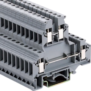
Multi-Level Terminal Blocks: Double the Circuits in a Single DIN Rail Space
A multi-level terminal block packs two or more electrical connection layers inside one insulated housing on a DIN rail. A double-level unit with 6.2 mm width gives each circuit just 3.1 mm of rail space—single-level blocks need 6.2 mm per circuit. For 24 circuits, double-level blocks occupy 74 mm of rail versus 149 mm with single-level equivalents. That is a 75 mm saving, or 50% less rail space.
Space Savings: The Real Numbers
Single-level terminal blocks force horizontal expansion across the DIN rail—each new circuit adds another block. Multi-level designs grow vertically, leaving room for PLCs, power supplies, and contactors.
Key space-saving facts:
-
A double-level block holds two independent circuits in the same width as one single-level unit
-
Triple-level versions pack three circuits into that same footprint
-
Multi-level configurations can save more than 50% of DIN rail room
| Configuration | Circuits per Block | Width per Circuit | Rail Space for 24 Circuits |
|---|---|---|---|
| Single-level | 1 | 6.2 mm | 149 mm |
| Double-level | 2 | 3.1 mm | 74 mm |
| Triple-level | 3 | 2.1 mm | 50 mm |
Four-Step Selection Process
Step 1: Count total circuits and map functions to levels. List every signal, power, and return path required. Assign each circuit to a specific level—for example, inputs on the upper level, outputs on the lower. This prevents cross-level confusion during installation.
Step 2: Verify current and voltage ratings against system requirements. Check the nominal current (typically 32 A) and rated voltage (500 V) against your application. The rated cross section ranges from 0.2 mm² to 4 mm² (22–12 AWG). A higher rating does not always mean a better block—current capacity depends on contact design and thermal conditions, not terminal opening size alone.
Step 3: Select the connection method. Screw connection remains the most widely used termination for multi-level terminal blocks. Each level operates independently with its own clamp positions. Spring-cage or push-in variants offer tool-free insertion of solid or ferruled conductors—these are better suited for high-vibration environments since they do not require retightening.
Step 4: Confirm DIN rail profile and accessory compatibility. Multi-level terminal blocks mount on standard 35 mm top-hat rails (NS 35/7.5 or NS 35/15 profiles) per IEC 60715. Universal mounting feet support both Ω-profile and G-profile rails. End stops secure the assembly and prevent lateral movement. Check that plug-in bridges (2-, 3-, or 10-pole configurations) are available for the selected block family.
Installation Checklist
| Step | Tool / Accessory | Note |
|---|---|---|
| Mount on DIN rail | NS 35/7.5 or NS 35/15 per IEC 60715 | Snap into place; secure both ends with end stops |
| Bridge adjacent blocks | 2-/3-/10-pole plug-in bridges | Match pole count to the number of circuits being connected |
| Apply torque to screw terminals | Screwdriver, set to 0.5–0.6 N·m for M3 screws | Re-torque after 24 hours—thermal cycling can loosen initial connections |
| Label each level | ZB6-type marking tags | Use color-coded markers (red for power, blue for signal) to speed up field maintenance |
For vibration-prone installations such as railway or mobile equipment, spring-cage terminals offer an advantage. They maintain consistent clamping force without periodic retorquing and meet IEC 61373 Category 1 Class B shock and vibration requirements. Screw-type clamps with steel and zinc plating also provide high locking action but require torque verification during routine maintenance.
Technical Specifications at a Glance
Multi-level terminal blocks are manufactured to meet stringent safety and performance standards.
Rated values (typical):
-
Voltage: 500 V
-
Current: up to 32 A
-
Conductor cross section: 0.2–4 mm² (22–12 AWG)
Material and safety:
-
Housing: Polyamide (PA) with UL 94 V-0 flame retardant rating—self-extinguishing material that minimizes fire spread
-
Clearance and creepage distances: Compliant with IEC 60947-7-1:2025 requirements
-
DIN rail mounting: Per IEC 60715 for 35 mm rails
IEC 60947-7-1:2025 applies to terminal blocks with screw-type or screwless-type clamping units for industrial use, covering structural requirements including clamping units, mounting, clearances, creepage distances, marking, and resistance to abnormal heat and fire.
Common Selection Mistakes to Avoid
Q: Can I use multi-level terminal blocks in high-vibration environments?
Yes—but choose the right type. Spring-cage terminals maintain contact without retightening and comply with IEC 61373 for railway rolling stock equipment. Screw-type terminals can also work but require periodic torque checks and locking hardware.
Q: Does a higher current rating always mean a better block?
No. Current rating depends on contact resistance, thermal dissipation, and conductor cross section—not terminal size alone. Always match the block's rated cross section to your actual wire gauge. Overspecifying can lead to unnecessary panel cost without performance gains.
Q: Can I mix copper and aluminum conductors in the same clamp?
Only if the terminal block is specifically rated for bi-metallic connections. Most multi-level terminal blocks are designed for copper conductors only. Mixing metals without proper rating causes galvanic corrosion and increased contact resistance over time.
For detailed torque specifications, wiring diagrams, and compatibility charts, please visit www.hangdaele.com. Proper selection and installation of multi-level terminal blocks deliver higher wiring density, lower installed cost, and cleaner panel layouts—especially when rail space is tight.