Matching Terminal Block Accessories To Voltage And Current Distribution Needs
Terminal block accessories—jumper strips, cover plates, end brackets, and test plugs—enable potential distribution by creating common electrical buses across terminal rows while ensuring circuit isolation and touch protection. Jumper strips carry the primary distribution load with current ratings from 15A to 41A, while end brackets secure the assembly to DIN rails and cover plates prevent accidental contact with live circuits. Cover plates and test plugs provide up to 600V isolation and live-system verification without service interruption.
Functional Overview of Terminal Block Accessories in Potential Distribution
Each accessory serves a distinct role in the distribution system. Jumper strips create the electrical pathway. Cover plates isolate and protect. End brackets provide mechanical stability. Test plugs enable verification. These four components work as a system—potential distribution is not a single accessory function but a coordinated assembly.
-
Jumper strips — bridge adjacent terminals to form a common electrical bus
-
Cover plates — cover exposed terminal sides for touch protection
-
End brackets — lock terminal blocks onto DIN rails
-
Test plugs — provide access points for measurement equipment
Selection Matrix for Potential Distribution Accessories
| Selection Criteria | Jumper Strip | Cover Plate | End Bracket | Test Plug |
|---|---|---|---|---|
| Primary Function | Electrical bridging | Isolation & protection | Mechanical securing | Live-system verification |
| Current Rating | 15A – 41A | N/A (non-conductive) | N/A (non-conductive) | Signal-level only |
| Voltage Rating | Up to 600V | Up to 600V | N/A | Up to 600V |
| Key Material | Copper | PA (V0 rated) | PA (V0 rated) | PA (V0 rated) |
| Mounting Compatibility | Terminal pitch matching | Snap-on | 32/35 mm DIN rail | Function shaft insertion |
Current demand determines the jumper strip selection起点. Voltage level and safety requirements dictate the material grade for cover plates and end brackets. Maintenance frequency determines whether test plug access points are necessary.
Component-by-Component Selection Guide
Jumper Strips – Sizing the Primary Conductive Path
Terminal block jumper strips are available with up to 50 contact tabs, enabling connection of multiple potentials across extensive terminal assemblies. Selection parameters include:
-
Pole count — must match the number of terminals being bridged; available from 2 to 50 poles
-
Rated current — common range from 15A to 41A
-
Pole spacing (pitch) — must precisely match the terminal block channel pitch
-
Material — copper conductor
Selection principle: the jumper strip current rating must equal or exceed the system maximum load current. An undersized strip overheats and fails. A common error is using a strip with insufficient poles for partial bridging, which creates open circuits.
Cover Plates and End Brackets – Protection and Mechanical Integrity
Terminal block cover plates cover the open sides of terminal rows, providing electrical isolation and touch protection. They must match the exact terminal series—not every accessory fits every terminal universally. V0 flammability rating (UL 94) is the industrial standard for control cabinets.
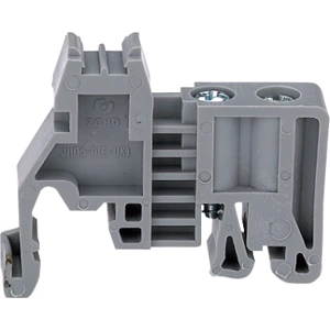
Terminal block cover components like end brackets serve a different function. They lock terminal blocks onto DIN rails, preventing mechanical displacement that could loosen jumper contacts. The JHD5-D end bracket, for example, measures 9.5 mm in thickness, 36.5 mm in height, and 44 mm in width, with gray PA construction and V0 flammability rating. It is compatible with standard 32 mm or 35 mm DIN rails (EN 60715). Proper mounting prevents lateral movement that increases contact resistance and generates heat.
Test Plugs – Verification Without System Shutdown
Terminal block test plugs insert into the function shaft of disconnect-type terminals, providing access points for measurement probes. The solid end plugs into the connection channel while the hollow end accepts testing instruments. Applications include:
-
Monitoring voltage and current in industrial control panels
-
Signal detection on voltage and current transformers
-
Verification of potential distribution quality without de-energizing circuits
Selection note: test plug width must match the corresponding terminal series width. Test plugs are particularly valuable in systems where downtime is costly.
Decision Table – Which Accessory for Which Application
| Application Scenario | Required Accessories | Selection Priority |
|---|---|---|
| Single incoming potential feeding multiple outgoing circuits | Jumper strip | Current rating > pole count |
| High-voltage terminal row (600V+) with exposed ends | Cover plate + End bracket | V0 rating + rail compatibility |
| Frequent maintenance and performance verification | Test plug + Cover plate | Function shaft access + isolation |
| Space-constrained control cabinet | End bracket (slim profile) | Thickness ≤ 9.5 mm |
| Multi-voltage distribution with circuit separation | Cover plate (partition type) | Voltage isolation rating |
Selection should start from the complete current path, not from isolated individual accessories.
Common Misconceptions in Accessory Selection
-
"Any cover plate fits any terminal." — Cover plates must match the exact terminal series. Model mismatch prevents snapping into place or eliminates touch protection.
-
"End brackets only secure mounting." — End brackets also prevent lateral displacement, which would increase contact resistance on jumper strips and cause overheating.
-
"Test plugs can be inserted anywhere." — Test plugs must insert into designated function shafts. Insertion into the wrong position may damage internal terminal structures.
-
"Current rating is the only jumper specification." — Pole spacing (pitch) must also match. Pitch mismatch prevents full insertion of the jumper strip.
Final Selection Checklist
-
Confirm the system maximum operating current and select a jumper strip with a rating ≥ that value
-
Confirm terminal block pole count and channel pitch, match jumper strip pole count and pitch
-
Confirm DIN rail specification (32 mm or 35 mm) and select a compatible end bracket
-
Confirm the working environment flammability rating requirement (V0 is the industrial standard)
-
Determine whether maintenance requires live-system verification—reserve test plug access points if needed
-
Confirm all accessories are compatible with the exact terminal family—match every end plate, end stop, jumper, and test part to the exact terminal series