Screw Type Terminal Blocks: Torque Specs, Wiring Steps & Failure Fixes
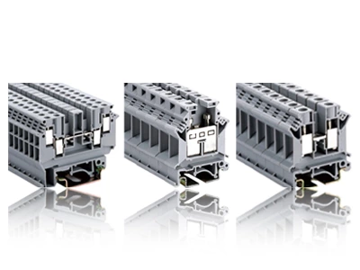
Screw type terminal blocks use a screw-driven clamp to press the conductor against a current bar, forming a gas-tight, low-resistance joint. Selection requires three fixed metrics: current rating derated to 80% for panel internal temperature rise, wire gauge compatibility (typically 26 AWG to 2 AWG), and torque specification (M2.5 screws: 0.5–0.6 N·m).
Torque Relaxation — Why 0.8 N·m Drops to 0.5 N·m After 72 Hours
A DIN rail screw terminal block torqued to 0.8 N·m during assembly often reads 0.5 N·m or below when re-inspected 72 hours later. This phenomenon, torque relaxation (also called stress relaxation or embedment relaxation), is a primary cause of loose connections and thermal runaway in industrial panels.
Three Physical Drivers
-
Cold flow (creep) of copper conductors — copper deforms plastically under sustained pressure, reducing the gap and the elastic energy stored in the screw.
-
Embedment relaxation — micro-asperities at conductor-to-contact and screw-to-thread interfaces flatten, absorbing elastic strain.
-
Thermal cycling — every on/off load cycle causes differential expansion between the copper conductor, the steel screw, and the brass or copper alloy body, accelerating creep.
At elevated temperatures above 60°C inside an enclosure, the drop is more severe. Unlike spring-cage designs that maintain constant force without re-torque, screw terminals allow field adjustment to compensate for this creep over the equipment lifecycle.
Wiring Installation Steps
Follow this sequence for every clamp type terminal blocks connection:
-
De-energize and verify — Lock out the circuit and confirm zero voltage with a multimeter.
-
Strip the conductor — Remove exactly the length specified on the housing (typically 7–10 mm for 2.5 mm² terminals). Over-stripping exposes live copper; under-stripping traps insulation under the clamp.
-
Insert the wire fully — Push the stripped conductor into the clamping body until it reaches the stop. For stranded wire, add a ferrule — this alone prevents roughly 80% of loose-connection failures. For a thermocouple screw terminal, fine-gauge thermocouple wires require a flat-blade pressure plate to prevent strand shearing — a feature absent in standard clamp terminal blocks.
-
Torque to specification — Use a calibrated torque screwdriver. Most 2.5 mm² screw-type blocks require 0.5–0.6 N·m. Over-tightening strips threads; under-tightening raises contact resistance and generates heat.
-
Pull-test the connection — Gently tug each wire (20 N pull) to confirm mechanical capture.
-
Label both ends — Use heat-shrink or printed wire markers matching the schematic tag.
-
Test the connection — Re-energize and verify voltage and continuity.
Common Installation Errors
Field data shows that most terminal block failures in PLC panels trace back to five repeatable errors:
-
Mixing signal and power conductors on the same rail — capacitive and inductive coupling injects common-mode noise into low-level signals.
-
Selecting the wrong terminal type (screw vs. push-in vs. spring-cage) for the vibration environment, current rating, or wire gauge.
-
Poor ferrule crimping and conductor stripping — over-stripped conductors, missing ferrules, or incorrect crimp dies.
-
No thermal spacing allowance — violating NFPA 79 bend radius and UL 508A wire bending space rules.
-
Illegible, inconsistent, or missing wire labels.
Fixing these five eliminates an estimated 70–80% of field commissioning callbacks.
Screw vs. Spring-Cage — Selection Trade-offs
| Parameter | Screw-Clamp | Spring-Cage |
|---|---|---|
| Connection force | User-applied via screw torque | Factory-set spring pressure |
| Installation tool | Screwdriver (flat or Phillips) | Push-in or actuation lever |
| Vibration behavior | Good, with periodic re-torque recommended | Excellent, maintenance-free |
| Conductor preparation | Ferrules optional for fine strands | Ferrules recommended for all stranded wire |
| Re-wiring cycles | Multiple cycles, no force degradation | Limited cycles, spring may fatigue |
| Installation time | ~30 seconds per wire | ~10 seconds per wire |
Screw terminals' irreplaceable scenario: Unlike spring-cage designs, screw terminals allow field adjustment of clamping force to compensate for wire creep (cold flow) over a 10-year lifecycle — a requirement for UL 1059 power distribution circuits. Larger conductors and higher-power connections typically use screw terminals.
Performance Verification per IEC & UL Standards
Temperature rise test (IEC 60947-7-1) : The standard permits a maximum rise of 45 K above ambient at rated current. Temperature rise tests are followed by voltage-drop measurements that indirectly validate clamping force retention.
Torque and wire gauge reference (UL 1059) :
| Wire Gauge | Typical Current Rating | Typical Tightening Torque |
|---|---|---|
| 2.5 mm² (14 AWG) | ≤24 A | 0.5–0.6 N·m |
| 4 mm² (12 AWG) | ≤32 A | 0.6–0.8 N·m |
Field Troubleshooting — Symptoms, Mechanisms & Fixes
Screw clamp terminals suffer three dominant failure modes in field operation: poor contact, abnormal overheating, and insulation breakdown.
Symptom-Mechanism Reference Table
| Observed Symptom | Likely Mechanism | Verification Method |
|---|---|---|
| Single terminal hot | Loose, overtightened, corroded, or poorly prepared conductor | Thermal comparison, de-energized inspection, voltage drop |
| Entire row hot | Overload, high ambient temperature, dense layout | Current measurement, panel ambient check |
| Terminal heats after vibration | Connection technology or strain relief unsuitable | Observe trend, inspect de-energized |
Diagnostic workflow:
-
Observe — Document the location and damage pattern. Record circuit, load, environment, adjacent terminals, and event history.
-
Compare — Check equivalent terminals under similar load on the same phase or circuit function.
-
Test — Use thermal imaging to screen anomalies; perform resistance, voltage drop, and load data checks.
-
Verify — Replace damaged components, correct the wiring process or environment, and recheck under representative load.
Selection Checklist
When specifying screw type terminal blocks for a control cabinet or junction box:
-
Rated current and voltage — select values exceeding the circuit's maximum operating parameters with adequate thermal margin
-
Wire cross-section range — verify the terminal accepts the intended conductor sizes, from 0.08 mm² to 35 mm²
-
Pitch and pole count — determine available panel space and required circuit density (pitches from 3.5 mm to 15 mm)
-
Accessories availability — confirm jumpers, end brackets, and partition plates are available for the chosen family
-
Standard certifications — verify UL 1059, IEC 60947-7-1, and other applicable standards