Feed-Through Terminal Blocks Selection Guide: Panel Pass-Through vs. Multi-Conductor vs. Multi-Level
Engineers choosing among three terminal block types—feed through terminal blocks, multi conductor terminal blocks, and multi level terminal blocks—face a common decision dilemma. The choice reduces to three questions: Does the circuit need to pass through a panel? Does the same potential require distribution to multiple loads? Is DIN rail space limited? Feed-through terminals offer the lowest series resistance with single-plane wiring. Multi-conductor blocks consolidate potential distribution into fewer modules. Multi-level blocks deliver the highest wiring density per rail position. Answer these three questions, and the selection direction becomes clear.
Feed-Through vs. Multi-Conductor vs. Multi-Level — Core Architecture Differences
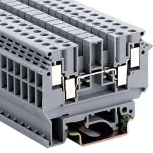
Feed through terminal blocks feature a continuous current bar running straight from the input side to the output side, with one conductor connected per side. This architecture eliminates intermediate splices and jumper wires, delivering the lowest contact resistance and the highest circuit integrity per path.
Multi-conductor terminal blocks are essentially feed-through variants—three or four conductors route through the same current bar on a single side. The advantage: fewer modules for potential distribution. The trade-off: all conductors share one electrical node, offering no isolation between circuits.
Multi level terminal blocks stack two or more wiring levels vertically within one housing footprint. The advantage: exceptional wiring density—two or three independent circuits occupy the space of one standard block. The trade-off: lower-level terminals become difficult to access once upper levels are wired.
Which Terminal Block Fits Your Application
| Parameter | Feed-Through | Multi-Conductor | Multi-Level |
|---|---|---|---|
| Conductors per block | 2 (one per side) | 3–4 (same side, shared bar) | 2+ per level |
| Electrical isolation | Full isolation per conductor | Shared node — no isolation | Independent per level |
| Panel pass-through capability | Yes | No | No |
| Wiring accessibility | All terminals on one plane | All on one plane | Lower levels blocked by upper wiring |
| Space efficiency on DIN rail | Baseline | Fewer blocks for same conductor count | Highest density per rail position |
| Typical use case | Panel pass-through, point-to-point | Common potential distribution | I/O-dense, space-constrained cabinets |
Multi-conductor terminal blocks excel when distributing a single potential—such as a 24 V DC supply bus—to multiple loads. Multi-level terminal blocks offer a decisive advantage in I/O-dense applications where DIN rail space is at a premium. Feed through terminals remain irreplaceable for panel pass-through, circuit independence, and the lowest series resistance per conductor path.
Feed-Through Terminal Blocks — Installation and Sizing in Practice
Panel Thickness and Creepage Distance
Feed through modular terminal block designs incorporate hook-and-socket mounting structures that snap into rectangular panel cutouts without screws or brackets. These structures accommodate panel thicknesses ranging from 1 mm to 10 mm, with the housing automatically compensating for variations.
Selection must verify creepage distance and clearance—the shortest paths along insulating surfaces and through air, respectively. Both parameters are governed by working voltage, pollution degree, and the material's CTI value. Interchangeable isolation plates inserted between adjacent poles increase creepage distances without altering the mounting footprint.
Torque and Conductor Range
M3 clamping screws with a specified tightening torque secure conductors ranging from 0.2 mm² to 6 mm² (solid). Common installation errors include:
-
Insufficient torque: contact resistance rises, causing temperature rise beyond acceptable limits
-
Excessive torque: conductor damage, particularly with stranded flexible wires
-
Incorrect stripping length: the conductor fails to seat fully in the clamping yoke, reducing contact area
For stranded flexible conductors above 2.5 mm², engineering practice recommends using ferrules to maintain consistent contact pressure and prevent strand spreading under clamp force.
Temperature Range and Housing Material
PA66 insulating housings carry a UL94 V-0 flammability rating—a baseline requirement for industrial environments. The operating temperature range typically spans -40°C to +110°C. In high-temperature, high-humidity conditions, torque values may require periodic rechecking: polyamide materials absorb moisture and undergo dimensional changes that affect clamping force over time.
Three Application Scenarios Where Feed-Through Terminal Blocks Excel
-
Control cabinet pass-through wiring: Route power and signal conductors from external field devices into enclosed control cabinets. Provide accessible termination points inside the cabinet while maintaining the panel's IP protection rating.
-
Battery and power supply connections: Connect battery banks through panel walls to external loads. Eliminate exposed cables passing through panel openings and reduce short-circuit risks.
-
EMI filter and variable frequency drive installations: Integrate feed-through terminals with filter assemblies. Carry filtered power across shielded barriers without compromising electromagnetic compatibility performance. These feed through terminal blocks are standard solutions for pass-through power delivery in drives, power supplies, and sealed equipment.
Standards Compliance — IEC 60947-7-1 and UL 1059
Feed-through terminal blocks must comply with IEC 60947-7-1, which specifies requirements for terminal blocks with screw-type or screw-less clamping units primarily intended for industrial use. The standard applies to blocks connecting round copper conductors, with or without special preparation, in circuits rated up to 1,000 V AC or 1,500 V DC.
UL 1059 covers terminal blocks rated 1,500 volts or less, addressing assemblies of wiring terminals and supporting blocks intended for wiring connections. These terminal blocks are intended to permanently support and insulate wire terminations and joints from each other and from the mounting surface. Products with UL recognition carry North American market compliance standing.
Specifying "Compliant with IEC 60947-7-1" and "UL Recognized" in selection documentation establishes technical credibility and simplifies equipment approvals.
Start with the Panel Pass-Through Question
The selection starting point remains the same question: Does the circuit need to cross a physical barrier—panel, cabinet wall, or chassis? If yes, feed through terminal blocks are the correct choice. Their continuous current bar delivers the lowest series resistance and the cleanest pass-through wiring.
If no panel pass-through is required but common potential distribution is needed, multi conductor terminal blocks accomplish the task with fewer modules. If DIN rail space is severely constrained and no pass-through is required, multi level terminal blocks deliver the highest wiring density.
Each type serves a distinct purpose. The selection decision starts with the pass-through requirement and ends with the trade-off between space and isolation.