EPDM Cold Heat Shrink Tubing Sizes and Cable Sleeve
- Power Frequency Withstand Voltage:
- 39 kV, 5 min, no breakdown
- Partial Discharge Test:
- Partial Discharge Magnitude≤ 10 pC at 15 kV
- Impulse Voltage Test:
- 95 kV, 10 positive and 10 negative impulses, no breakdown
- Constant Voltage Load Cycling Test (in Air):
- 23 kV, conductor temperature 95–100 ℃, total 60 cycles, no breakdown, no flashover
- Thermal Stability Test (185 mm² Conductor):
- 23.4 kA, 2 s, twice, no visible damage
- Dynamic Stability Test:
- 82.6 kA, ≥ 10 ms, no visible damage
- Moisture Test (Indoor):
- 11 kV, 300 h, no breakdown, no flashover
- Salt Spray Test (Outdoor):
- 11 kV, 1000 h, no breakdown, no flashover
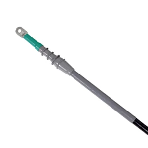
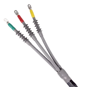
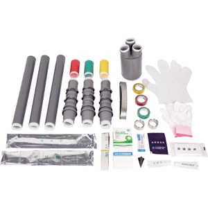
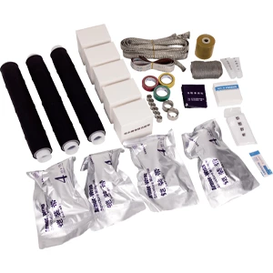
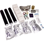
Why do medium-voltage joints deteriorate during thermal cycling? Air voids trapped during flame shrinkage remain the leading cause of electrical breakdown. Deploying an epdm cold shrink tube resolves this failure mode, as constant radial tension automatically contracts around polymeric insulation during high-load temperature swings.
Radial Seal Integrity in Substation Environments
Elastomeric compounds maintain dynamic sealing without open flame permits or gas canisters:
-
Active pressure prevents moisture tracking across metallic shielding.
-
High dielectric strength stops partial discharge along outer semiconductor interfaces.
-
Where conventional cold heat shrink retrofits degrade, cross-linked rubber preserves elastic recovery.
Dimensional Sizing Matrix for 8.7/15 kV Circuits
A pre-expanded cold shrink sleeve requires precise dimensional matching to prevent slip or over-expansion stress on the core.
| Rated Voltage (kV) | Conductor Cross-Section (mm²) | Insulation Outer Diameter (mm) | Dielectric Strength (kV/mm) |
|---|---|---|---|
| 8.7/15 | 25 – 50 | 16.0 – 24.5 | ≥ 20 |
| 8.7/15 | 70 – 120 | 21.5 – 32.0 | ≥ 20 |
| 8.7/15 | 150 – 240 | 26.5 – 38.5 | ≥ 20 |
| 8.7/15 | 300 – 400 | 34.0 – 46.0 | ≥ 20 |
Pre-Installation Verification Steps
Selecting incorrect dimensions risks insulation puncture or loose radial grip. Follow this verification sequence:
-
Measure cable insulation diameter after stripping the semiconductive screen.
-
Confirm cold shrink tubing sizes provide at least 15% elastomeric interference fit.
-
Ensure adequate enclosure clearance for removing the internal spiral core.
Procure Tested Medium-Voltage Terminations
Eliminating partial discharge begins at the specification phase, well before trench work starts. To match precise conductor dimensions with factory-tested Cold Shrink Cable Accessories, consult the complete 8.7/15 kV selection program to secure durable, flame-free underground distribution.
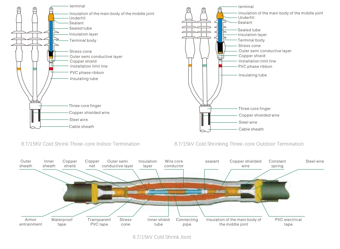
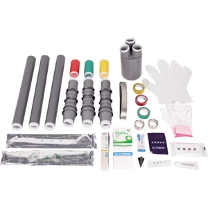
8.7/15 kV Fully Cold Shrink Three-Core Terminal – Installation Outline Drawing
Electrical Performance Tests
| No. | Test Item | Standard Requirements |
| 1 | Power Frequency Withstand Voltage | 39 kV, 5 min, no breakdown |
| 2 | Partial Discharge Test | Partial Discharge Magnitude≤ 10 pC at 15 kV |
| 3 | Impulse Voltage Test | 95 kV, 10 positive and 10 negative impulses, no breakdown |
| 4 | Constant Voltage Load Cycling Test (in Air) | 23 kV, conductor temperature 95–100 ℃, total 60 cycles, no breakdown, no flashover |
| 5 | Thermal Stability Test (185 mm² Conductor) | 23.4 kA, 2 s, twice, no visible damage |
| 6 | Dynamic Stability Test | 82.6 kA, ≥ 10 ms, no visible damage |
| 7 | Moisture Test (Indoor) | 11 kV, 300 h, no breakdown, no flashover |
| 8 | Salt Spray Test (Outdoor) | 11 kV, 1000 h, no breakdown, no flashover |
Product overview
◆The product is available in single-core, two-core, three-core, four-core, and five-core versions, and has been widely used for low-voltage cable terminations and intermediate connections.
◆Excellent surface hydrophobicity, ensuring the product maintains strong resistance to contamination.
◆Compact size, lightweight, and reliable performance.
◆Application Scope: The product demonstrates excellent cold and heat resistance, making it particularly suitable for high-altitude, cold, humid, salt-spray, and heavily polluted environments.
Installation requires no open flame, making it ideal for flammable and explosive areas such as petroleum, chemical, mining, and tunneling sites.
 |
 |
 |
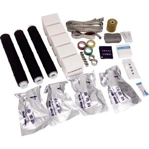 |
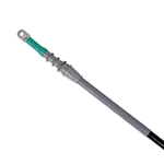
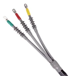
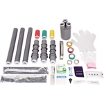
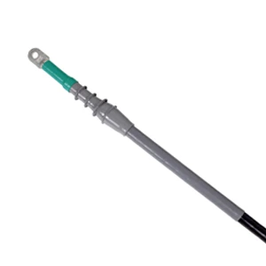
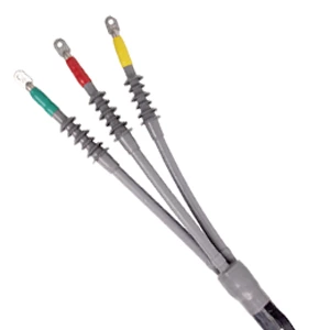
| 8.7/15 kV Single-Core Cold Shrink Indoor Termination – Installation Drawing | 8.7/15 kV Three-Core Cold Shrink Outdoor Termination – Installation Drawing | 8.7/15 kV Three-Core Cold Shrink Outdoor Termination – Supporting Drawing | 8.7/15 kV Three-Core Cold Shrink Joint – Supporting Drawing |
Technical Data - Model Selection
| Product Type | Model | Conductor Cross-section(mm²) | Product Type | Model | Conductor Cross-section(mm²) | |||
| 8.7/15 kV Three core cold shrink indoor terminal | GHD-15HNLS-3*25-50 | 25-50 | 8.7/15 kV Single core cold shrink indoor terminal | GHD-15HNLS-1*25-50 | 25-50 | |||
| GHD-15HNLS-3*70-120 | 70-120 | GHD-15HNLS-1*70-120 | 70-120 | |||||
| GHD-15HNLS-3*150-240 | 150-240 | GHD-15HNLS-1*150-240 | 150-240 | |||||
| GHD-15HNLS-3*300-400 | 300-400 | GHD-15HNLS-1*300-400 | 300-400 | |||||
| 8.7/15 kV Three core cold shrink outdoor terminal | GHD-15HWLS-3*25-50 | 25-50 | 8.7/15 kV Single core cold shrink outdoor terminal | GHD-15HWLS-1*25-50 | 25-50 | |||
| GHD-15HWLS-3*70-120 | 70-120 | GHD-15HWLS-1*70-120 | 70-120 | |||||
| GHD-15HWLS-3*150-240 | 150-240 | GHD-15HWLS-1*150-240 | 150-240 | |||||
| GHD-15HWLS-3*300-400 | 300-400 | GHD-15HWLS-1*300-400 | 300-400 | |||||
| 8.7/15 kV Three core cold shrink intermediate joint | GHD-15JTLS-3*25-50 | 25-50 | 8.7/15 kV Single core cold shrinkintermediate joint | GHD-15JTLS-1*25-50 | 25-50 | |||
| GHD-15JTLS-3*70-120 | 70-120 | GHD-15JTLS-1*70-120 | 70-120 | |||||
| GHD-15JTLS-3*150-240 | 150-240 | GHD-15JTLS-1*150-240 | 150-240 | |||||
| GHD-15JTLS-3*300-400 | 300-400 | GHD-15JTLS-1*300-400 | 300-400 | |||||
