
How One Size Cold Shrink Cable Accessories Covers 240–630mm²: The Physics Behind Wide-range Adaptability
- Power Frequency Withstand Voltage:
- 39 kV, 5 min, no breakdown
- Partial Discharge Test:
- Partial Discharge Magnitude≤ 10 pC at 15 kV
- Impulse Voltage Test:
- 95 kV, 10 positive and 10 negative impulses, no breakdown
- Constant Voltage Load Cycling Test (in Air):
- 23 kV, conductor temperature 95–100 ℃, total 60 cycles, no breakdown, no flashover
- Thermal Stability Test (185 mm² Conductor):
- 23.4 kA, 2 s, twice, no visible damage
- Dynamic Stability Test:
- 82.6 kA, ≥ 10 ms, no visible damage
- Moisture Test (Indoor):
- 11 kV, 300 h, no breakdown, no flashover
- Salt Spray Test (Outdoor):
- 11 kV, 1000 h, no breakdown, no flashover
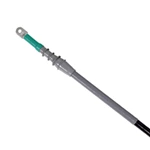
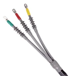


A single 35kV cold shrink cable accessory covers 240–630mm². Factory pre-expansion stores elastic memory inside the rubber. On site, the installer pulls the spiral core, and the material contracts onto the cable. One model replaces several fixed sizes. For medium voltage, one unit often covers 70–150mm². Selection follows insulation diameter, not conductor cross-section alone. Three steps: measure the insulation outside diameter, match it to the stated range, then pull the core and let the rubber recover.
Cold Shrink vs Heat Shrink: Why the Difference Matters
Cold shrink relies on elastic memory. Heat shrink relies on applied heat. Silicone rubber heat shrink tubing belongs to the heat-activated family and cannot explain cold shrink expansion ratios. Silicone shrink wrap often describes heat-shrink or wrap-around materials, not pre-expanded cold shrink parts.
-
Cold shrink: no flame, elastic memory, spiral core.
-
Heat shrink: heat source, cross-linked polyolefin, torch or oven.
Elastic Memory and Pre-Expansion Physics
Cross-Linking Locks the Molded Shape
Rubber compounds are cross-linked into a three-dimensional network. That network remembers the mold dimensions. The material cannot melt or be reshaped afterward.
Factory Pre-Expansion Stores Energy
The cured rubber is stretched radially beyond twice its original diameter. A rigid plastic spiral core holds that expanded shape. A higher expansion ratio stores more contraction energy.
Core Removal and Radial Recovery
The installer pulls the core. The rubber contracts evenly and grips the cable. Radial pressure at the interface controls sealing and electrical performance.
Permanent Set Decides Service Life
Permanent set measures how much an elastomer fails to recover. EPDM stays at 21% or less, with elongation above 300%. Lower set keeps radial pressure stable through thermal cycling.
Expansion Ratio Is Not the Only Number
| Parameter | Meaning | Typical Value | Standard |
|---|---|---|---|
| Expansion ratio | Coverage width | 2:1 to 5:1 | IEC 60502 |
| Permanent set | Service pressure | ≤21% | ASTM D2671 |
| Dielectric strength | Insulation ability | 23kV/mm | IEC 60502 |
| Temperature range | Environment fit | -60°C to 200°C | Material datasheet |
A wide ratio alone does not make selection flexible. A high ratio must pair with low permanent set.
From Conductor Size to Insulation Diameter
Why Conductor mm² Is Not Enough
Insulation thickness varies between cable types. A 240mm² and a 630mm² cable can present different outside diameters. The accessory matches diameter, not cross-section alone.
Four-Step Selection Method
-
Measure insulation outside diameter.
-
Check the product diameter range.
-
Verify expansion ratio and permanent set.
-
Confirm installation temperature and voltage class.
Calculation Example
A 35kV joint rated 240–630mm² accepts a defined insulation diameter band. If the measured outside diameter falls outside that band, choose another model. Cold shrink kits follow the same rule.
Coverage Examples with Source Notes
| Voltage | Single-Model Coverage | Expansion Ratio | Material |
|---|---|---|---|
| 35kV | 240–630mm² | ~2.6:1 | Silicone / EPDM |
| 18/30kV | 70–150mm² | ~2.1:1 | Silicone / EPDM |
| 8.7/15kV | 25–50mm² / 70–120mm² | ~2.0:1 | EPDM |
Values reference IEC 60502 and IEEE 404. They support selection but do not replace field measurement.
Common Selection Errors
-
Reading conductor size only and ignoring insulation diameter.
-
Treating silicone shrink wrap as a cold shrink product.
-
Pushing a unit beyond its expansion limit.
-
Ignoring permanent set and thermal cycling.
-
Damaging the rubber surface during installation.
-
Skipping the post-recovery pressure check.
Installation and Quality Checks
-
Clean the cable surface.
-
Mark the recovery position.
-
Pull the spiral core.
-
Check even contraction.
-
Run visual and electrical tests.
Cold shrink kits allow flame-free installation.
FAQ
Q: How can one cold shrink accessory cover 240–630mm²?
A: A pre-expansion ratio near 2.6:1 stores elastic memory. After core removal, the rubber contracts onto the cable.
Q: Is silicone rubber heat shrink tubing the same as cold shrink?
A: No. The first needs heat; the second uses elastic memory.
Q: Are cold shrink kits selected by conductor or insulation diameter?
A: Selection uses insulation outside diameter. Conductor size is a reference.
Q: What expansion ratio is typical?
A: Medium voltage units run 2:1 to 3.5:1. Silicone rubber can reach 5:1.
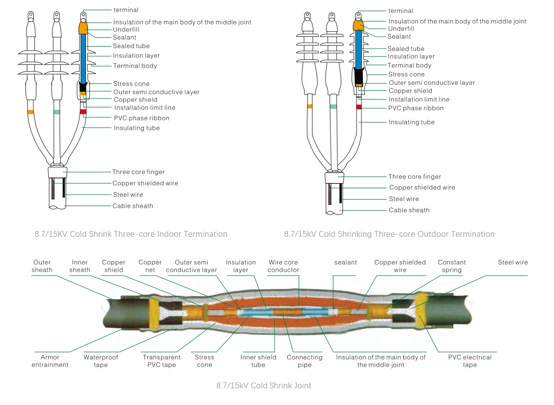
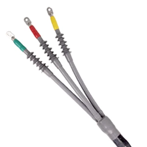
8.7/15 kV Fully Cold Shrink Three-Core Terminal – Installation Outline Drawing
Electrical Performance Tests
| No. | Test Item | Standard Requirements |
| 1 | Power Frequency Withstand Voltage | 39 kV, 5 min, no breakdown |
| 2 | Partial Discharge Test | Partial Discharge Magnitude≤ 10 pC at 15 kV |
| 3 | Impulse Voltage Test | 95 kV, 10 positive and 10 negative impulses, no breakdown |
| 4 | Constant Voltage Load Cycling Test (in Air) | 23 kV, conductor temperature 95–100 ℃, total 60 cycles, no breakdown, no flashover |
| 5 | Thermal Stability Test (185 mm² Conductor) | 23.4 kA, 2 s, twice, no visible damage |
| 6 | Dynamic Stability Test | 82.6 kA, ≥ 10 ms, no visible damage |
| 7 | Moisture Test (Indoor) | 11 kV, 300 h, no breakdown, no flashover |
| 8 | Salt Spray Test (Outdoor) | 11 kV, 1000 h, no breakdown, no flashover |
Product overview
◆The product is available in single-core, two-core, three-core, four-core, and five-core versions, and has been widely used for low-voltage cable terminations and intermediate connections.
◆Excellent surface hydrophobicity, ensuring the product maintains strong resistance to contamination.
◆Compact size, lightweight, and reliable performance.
◆Application Scope: The product demonstrates excellent cold and heat resistance, making it particularly suitable for high-altitude, cold, humid, salt-spray, and heavily polluted environments.
Installation requires no open flame, making it ideal for flammable and explosive areas such as petroleum, chemical, mining, and tunneling sites.
 |
 |
 |
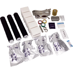 |
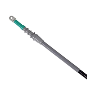
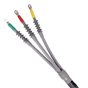
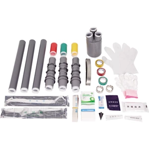
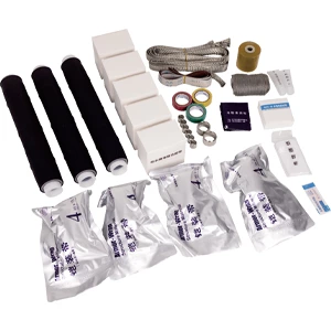
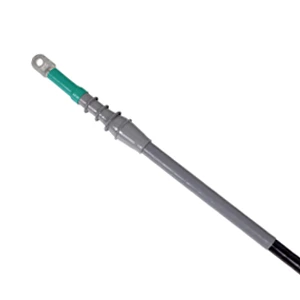
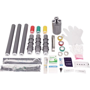
| 8.7/15 kV Single-Core Cold Shrink Indoor Termination – Installation Drawing | 8.7/15 kV Three-Core Cold Shrink Outdoor Termination – Installation Drawing | 8.7/15 kV Three-Core Cold Shrink Outdoor Termination – Supporting Drawing | 8.7/15 kV Three-Core Cold Shrink Joint – Supporting Drawing |
Technical Data - Model Selection
| Product Type | Model | Conductor Cross-section(mm²) | Product Type | Model | Conductor Cross-section(mm²) | |||
| 8.7/15 kV Three core cold shrink indoor terminal | GHD-15HNLS-3*25-50 | 25-50 | 8.7/15 kV Single core cold shrink indoor terminal | GHD-15HNLS-1*25-50 | 25-50 | |||
| GHD-15HNLS-3*70-120 | 70-120 | GHD-15HNLS-1*70-120 | 70-120 | |||||
| GHD-15HNLS-3*150-240 | 150-240 | GHD-15HNLS-1*150-240 | 150-240 | |||||
| GHD-15HNLS-3*300-400 | 300-400 | GHD-15HNLS-1*300-400 | 300-400 | |||||
| 8.7/15 kV Three core cold shrink outdoor terminal | GHD-15HWLS-3*25-50 | 25-50 | 8.7/15 kV Single core cold shrink outdoor terminal | GHD-15HWLS-1*25-50 | 25-50 | |||
| GHD-15HWLS-3*70-120 | 70-120 | GHD-15HWLS-1*70-120 | 70-120 | |||||
| GHD-15HWLS-3*150-240 | 150-240 | GHD-15HWLS-1*150-240 | 150-240 | |||||
| GHD-15HWLS-3*300-400 | 300-400 | GHD-15HWLS-1*300-400 | 300-400 | |||||
| 8.7/15 kV Three core cold shrink intermediate joint | GHD-15JTLS-3*25-50 | 25-50 | 8.7/15 kV Single core cold shrinkintermediate joint | GHD-15JTLS-1*25-50 | 25-50 | |||
| GHD-15JTLS-3*70-120 | 70-120 | GHD-15JTLS-1*70-120 | 70-120 | |||||
| GHD-15JTLS-3*150-240 | 150-240 | GHD-15JTLS-1*150-240 | 150-240 | |||||
| GHD-15JTLS-3*300-400 | 300-400 | GHD-15JTLS-1*300-400 | 300-400 | |||||
