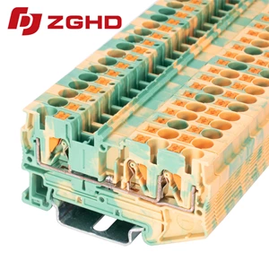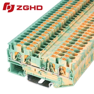
Push In DIN Rail Wire Connector Terminal Block Types
- Type:
- Protective conductor terminal block
- Number Of Connections:
- 2
- Connection Method:
- Push-in connection
- Rated Cross Section:
- 10 mm²
- Mounting type:
- DIN Rail (EN 60715)
- Compatible Rail:
- NS 35/7,5, NS 35/15
- Cross Section:
- 0.5 mm² - 16 mm²
- Color:
- green-yellow
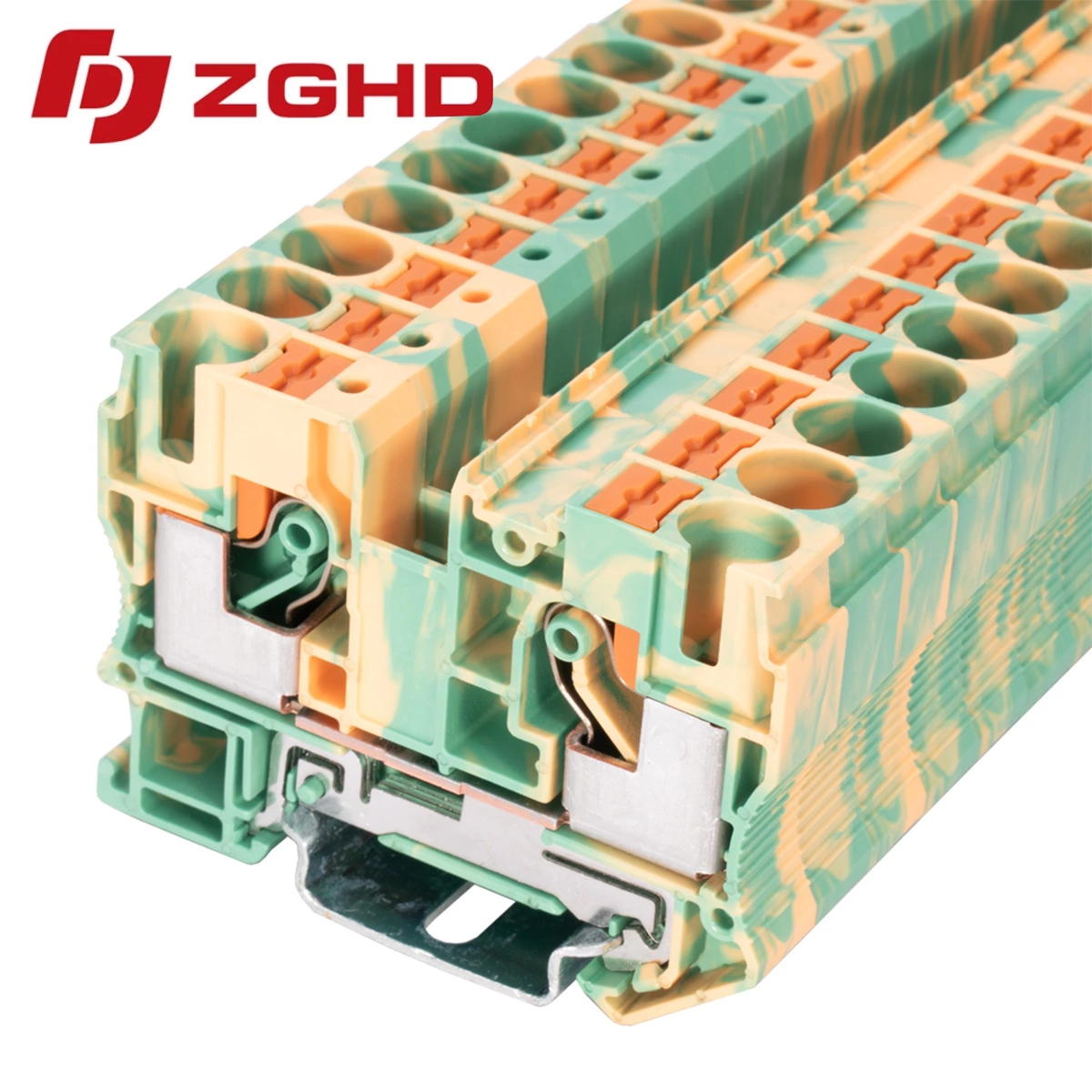
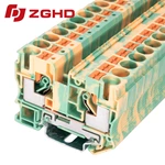
Loose screw joints cause sudden field downtime, while repetitive manual tightening slows down cabinet fabrication. Direct spring-cage clamping with push in type terminal blocks cuts termination time in half: rigid wires and ferruled leads lock firmly on contact, completely impervious to machine vibration.
Core Topologies Across Control Panels
Panel designs call for specialized configurations along the mounting rail:
-
Through-Wiring: Standard push in din rail terminal blocks route signals between compartments with negligible millivolt drop.
-
High-Density Distribution: Multi-level blocks stack two or three circuits vertically to maximize cramped rail space.
-
Component Isolation: Knife-disconnect modules open circuits instantly for routine diagnostics without unscrewing conductors.
-
Ground Protection: Earthing blocks discharge fault currents straight into the DIN rail structure.
High-Integrity Earthing Architecture
Transient electrical surges require robust protection. Deploying a dedicated push fit connector block prevents short-circuit damage to sensitive PLCs and drives. Choosing an IEC-compliant protective conductor terminal ensures low contact resistance via heavy-duty copper alloy clamps. Encased in halogen-free PA66 housing, each push in wire terminal block resists thermal cycling and mechanical fatigue under heavy industrial duty.
Electrical & Mechanical Specifications
| Parameter | Rating | Test Standard |
|---|---|---|
| Nominal Voltage | 800 V | IEC 60947-7-1 |
| Rated Current | 57 A | 10 mm² Rigid Lead |
| Contact Resistance | ≤ 0.5 mΩ | IEC 60947-7-2 |
| Wire Capacity | 0.5 – 10 mm² | Solid or Stranded |
| Flammability Rating | UL 94 V-0 | Vertical Flame Test |
Field Commissioning and Verification
Speed up panel sign-off with this three-step inspection workflow:
-
Conductor Insertion: Push stripped leads straight into the clamp until seated—no opening tools required.
-
Mechanical Pull Test: Tug gently to confirm that internal stainless leaf springs have locked the conductor securely.
-
Live Circuit Probing: Touch multimeter probes directly to the integrated test tap on each push fit terminal without disrupting live wiring paths.
| Wiring Diagram | 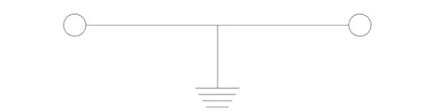 |
| Thickness/Witdh/Height | 10.2*68*50 mm |
| Nominal cross section | 10 mm² |
| Rated current | / |
| Rated voltage | / |
| Color | green-yellow |
| Insulating material | PA66 |
| Flame retardant rating UL-94 | V0 |
| Connection type | Push-in connection |
| The minimum cross section(Rigid wire) | 1.5 mm² |
| The maximum cross section(Rigid wire) | 16 mm² |
| The minimum cross section(Soft wire) | 1.5 mm² |
| The maximum cross section(Soft wire) | 16 mm² |
| Cover | JHD1-10G |
| Jumper | / |
| Marker | ZB10M |
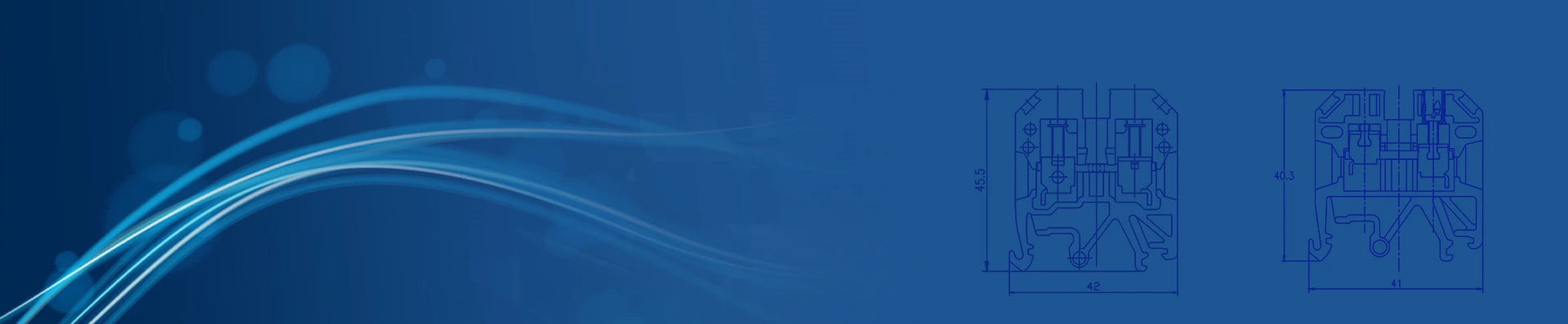
| Dimensions | 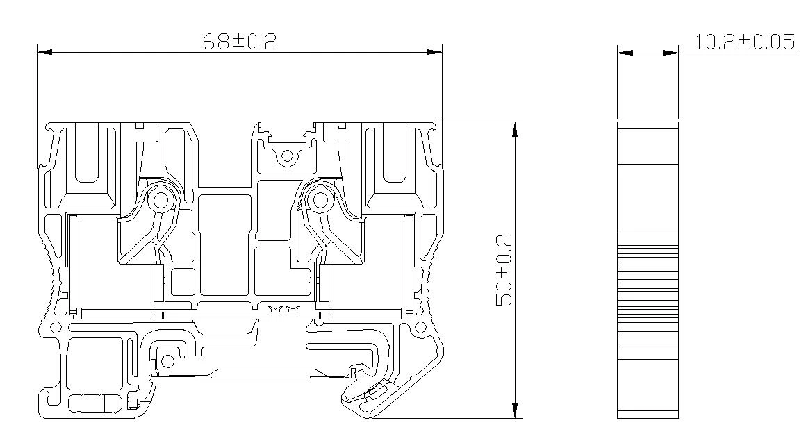 |