Cold Shrink Cable Accessories: Insulation OD Beats Cross-section
- Reference standards:
- JB/T7829,JB/T 7830
- AC Withstand Voltage for 5 min:
- 8 kV,no breakdown
- Heating Cycles Test in Air:
- 4.5 kV, heating cycles at least 8 h, 95–100 ℃ for at least 2 h, natural cooling for at least 3 h, total 30 heating cycles
- Heating Cycles Test Under Water:
- 4.5 kV, heating cycles at least 8 h, 95–100 ℃ for at least 2 h, natural cooling for at least 3 h, total 30 heating cycles
- AC Withstand Voltage:
- 7.2 kV,4 h no breakdown
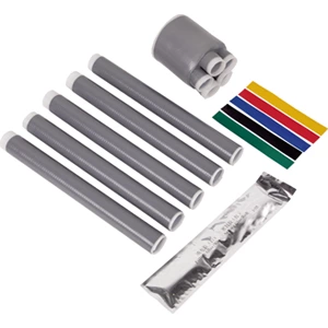


Choosing Cold Shrink Cable Accessories requires more than conductor cross-section. Insulation outer diameter determines whether the accessory body achieves proper interference fit. A mismatch leaves air gaps, triggers partial discharge, and shortens service life. Cross-section only guides connector size. Measure insulation OD first.
Why Conductor Cross-Section Alone Fails
Conductor cross-section and insulation OD do not track one-to-one. Two 95 mm² cables can differ by 8 mm or more in insulation diameter. Voltage class, insulation thickness, and manufacturing tolerances drive this gap. Selecting a cold shrink termination from cross-section alone ignores the dimension that controls electrical stress.
Three Variables That Shift Insulation OD
-
Voltage class: higher ratings require thicker insulation walls.
-
Manufacturing tolerances: catalog nominal values often differ from actual cable dimensions.
-
Insulation material and semi-conductive layers: XLPE and EPR compounds shrink differently during extrusion.
These variables affect the electric field stress at the cable shield cutback. A cold shrinkable tube sized without them may recover unevenly.
What Happens When Insulation OD Mismatches
Accessory Too Small
The rubber cannot reach its designed radial compression. Installation may tear the sleeve, or the loose fit creates voids that ionize under voltage.
Accessory Too Large
Recovered rubber lacks sufficient pressure. Sealing weakens, moisture enters, and stress control degrades.
A Practical Example
A 24 kV cold shrink termination rated for 27.8–33.5 mm insulation cannot fit a 95 mm² cable with 25 mm insulation. The 2.8 mm gap supports electrical treeing within months of service.
How to Measure and Select Correctly
-
Measure insulation OD with a caliper at three points. Average the readings.
-
Match the average to the accessory's insulation OD range, not conductor range.
-
Check connector or lug maximum diameter against the kit limit.
-
Confirm jacket OD for the cold shrink tubing that rebuilds the sheath.
-
Verify voltage class, indoor or outdoor use, and shield structure.
-
Review the cold shrinkable tube compression range.
| Parameter | Function | Typical Range |
|---|---|---|
| Conductor cross-section | Connector and lug size | 10–1000 mm² |
| Insulation OD | Accessory body size | 12–66 mm |
| Jacket OD | Re-jacketing sleeve size | 18–74 mm |
| Connector OD | Installation clearance | Per lug specification |
Product Sizing Example: 0.6/1 kV Cold Shrink Cable Accessories
A 0.6/1 kV product table lists voltage, conductor cross-section, insulation OD, and jacket OD for each model. Reading only the conductor column causes misorders. The insulation OD column narrows the correct kit.
How to Read the Product Table
Locate the cable's measured insulation OD. Find the row where that value falls inside the accessory's range. Then confirm jacket OD for the cold shrink tubing.
Common Misreads
-
Selecting from conductor cross-section only.
-
Ignoring jacket OD for the outer sleeve.
-
Skipping connector OD checks.
-
Overlooking installation environment.
Request the specification sheet or view the product page before ordering.
Common Mistakes and Fixes
-
Sizing from cross-section alone. Fix: measure insulation OD.
-
Using jacket OD to pick the accessory body. Fix: separate body and sleeve dimensions.
-
Ignoring connector OD. Fix: compare lug dimensions with kit limits.
-
Overlooking environment. Fix: match indoor, outdoor, or buried ratings.
-
Skipping field measurement. Fix: use a caliper on the prepared cable.
Correction Checklist
Confirm insulation OD, accessory range, cold shrink termination compression, and cold shrink tubing jacket range. A void-free interface depends on all four.
Installation Checks and Verification
Before Installation
Clean the cable, mark dimensions, and verify the accessory part number against measurements.
After Installation
Inspect the seal, confirm radial compression, and perform partial discharge testing. A proper fit shows uniform recovery without wrinkles or gaps.
FAQ
Q: Can cross-section alone determine Cold Shrink Cable Accessories size?
A: No. Insulation OD decides the accessory body. Cross-section guides connector choice.
Q: What if insulation OD falls between two sizes?
A: Choose the range giving proper radial compression. Confirm with the manufacturer.
Q: Does cold shrink tubing depend on jacket OD?
A: Yes. The re-jacketing sleeve must match the jacket outer diameter.
Q: How to verify a cold shrink termination fits?
A: Measure insulation OD, connector OD, and jacket OD. Compare all three with the product table.
0.6/1 kV Fully Cold Shrink Three-Core Terminal – Installation Outline Drawing

 |
 |
| 0.6/1 kV Five-Core Cold Shrink Terminal – Supporting Drawing | 0.6/1 kV Five-Core Cold Shrink Joint – Supporting Drawing |
Electrical Performance Tests
| No. | Test Item | Standard Requirements |
| 1 | AC Withstand Voltage for 5 min | 8 kV,no breakdown |
| 2 | Heating Cycles Test in Air | 4.5 kV, heating cycles at least 8 h, 95–100 ℃ for at least 2 h, natural cooling for at least 3 h, total 30 heating cycles |
| 3 | Heating Cycles Test Under Water | 4.5 kV, heating cycles at least 8 h, 95–100 ℃ for at least 2 h, natural cooling for at least 3 h, total 30 heating cycles |
| 4 | AC Withstand Voltage | 7.2 kV,4 h no breakdown |
| 5 | Reference Standards | JB/T7829,JB/T 7830 |
Product overview
◆The product is available in single-core, two-core, three-core, four-core, and five-core versions, and has been widely used for low-voltage cable terminations and intermediate connections.
◆Excellent surface hydrophobicity, ensuring the product maintains strong resistance to contamination.
◆Compact size, lightweight, and reliable performance.
◆Application Scope: The product demonstrates excellent cold and heat resistance, making it particularly suitable for high-altitude, cold, humid, salt-spray, and heavily polluted environments.
Installation requires no open flame, making it ideal for flammable and explosive areas such as petroleum, chemical, mining, and tunneling sites.
Technical Data - Model Selection
| Product Type | Model | Conductor Cross-section(mm²) | Product Type | Model | Conductor Cross-section(mm²) |
| 0.6/1 kV Single-Core Cold Shrink Termination | GHD-1LS-1*10-16 | 10-16 | 0.6/1 kV Single-Core Cold Shrink Joint | GHD-1JTLS-1*10-16 | 10-16 |
| GHD-1LS-1*25-50 | 25-50 | GHD-1JTLS-1*25-50 | 25-50 | ||
| GHD-1LS-1*70-120 | 70-120 | GHD-1JTLS-1*70-120 | 70-120 | ||
| GHD-1LS-1*150-240 | 150-240 | GHD-1JTLS-1*150-240 | 150-240 | ||
| GHD-1LS-1*300-400 | 300-400 | GHD-1JTLS-1*300-400 | 300-400 | ||
| 0.6/1 kV Two-Core Cold Shrink Termination | GHD-1LS-2*10-16 | 10-16 | 0.6/1 kV Two-Core Cold Shrink Joint | GHD-1JTLS-2*10-16 | 10-16 |
| GHD-1LS-2*25-50 | 25-50 | GHD-1JTLS-2*25-50 | 25-50 | ||
| GHD-1LS-2*70-120 | 70-120 | GHD-1JTLS-2*70-120 | 70-120 | ||
| GHD-1LS-2*150-240 | 150-240 | GHD-1JTLS-2*150-240 | 150-240 | ||
| GHD-1LS-2*300-400 | 300-400 | GHD-1JTLS-2*300-400 | 300-400 | ||
| 0.6/1 kV Three-Core Cold Shrink Termination | GHD-1LS-3*10-16 | 10-16 | 0.6/1 kV Three-Core Cold Shrink Joint | GHD-1JTLS-3*10-16 | 10-16 |
| GHD-1LS-3*25-50 | 25-50 | GHD-1JTLS-3*25-50 | 25-50 | ||
| GHD-1LS-3*70-120 | 70-120 | GHD-1JTLS-3*70-120 | 70-120 | ||
| GHD-1LS-3*150-240 | 150-240 | GHD-1JTLS-3*150-240 | 150-240 | ||
| GHD-1LS-3*300-400 | 300-400 | GHD-1JTLS-3*300-400 | 300-400 | ||
| 0.6/1 kV Four-Core Cold Shrink Termination | GHD-1LS-4*10-16 | 10-16 | 0.6/1 kV Four-Core Cold Shrink Joint | GHD-1JTLS-4*10-16 | 10-16 |
| GHD-1LS-4*25-50 | 25-50 | GHD-1JTLS-4*25-50 | 25-50 | ||
| GHD-1LS-4*70-120 | 70-120 | GHD-1JTLS-4*70-120 | 70-120 | ||
| GHD-1LS-4*150-240 | 150-240 | GHD-1JTLS-4*150-240 | 150-240 | ||
| GHD-1LS-4*300-400 | 300-400 | GHD-1JTLS-4*300-400 | 300-400 | ||
| 0.6/1 kV Five-Core Cold Shrink Termination | GHD-1LS-5*10-16 | 10-16 | 0.6/1 kV Five-Core Cold Shrink Joint | GHD-1JTLS-5*10-16 | 10-16 |
| GHD-1LS-5*25-50 | 25-50 | GHD-1JTLS-5*25-50 | 25-50 | ||
| GHD-1LS-5*70-120 | 70-120 | GHD-1JTLS-5*70-120 | 70-120 | ||
| GHD-1LS-5*300-400 | 150-240 | GHD-1JTLS-5*150-240 | 150-240 | ||
| GHD-1LS-5*300-400 | 300-400 | GHD-1JTLS-5*300-400 | 300-400 |
