Why Cold Shrink Cable Accessories Fail Less: Constant Radial Pressure And Field Optimization Explained
- Reference standards:
- JB/T7829,JB/T 7830
- AC Withstand Voltage for 5 min:
- 8 kV,no breakdown
- Heating Cycles Test in Air:
- 4.5 kV, heating cycles at least 8 h, 95–100 ℃ for at least 2 h, natural cooling for at least 3 h, total 30 heating cycles
- Heating Cycles Test Under Water:
- 4.5 kV, heating cycles at least 8 h, 95–100 ℃ for at least 2 h, natural cooling for at least 3 h, total 30 heating cycles
- AC Withstand Voltage:
- 7.2 kV,4 h no breakdown
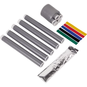


Cold shrink cable accessories resist failure through two mechanisms: sustained radial pressure that blocks moisture at the interface, and integrated stress control that prevents field concentration from eroding insulation. Both occur at the material level, independent of installation technique.
Two Mechanisms That Cut Failure Rates
-
Radial pressure: elastic memory forms a continuous seal
-
Field optimization: stress control tube removes partial discharge
-
Both work at the material layer, not through adhesive
What Causes Cable Accessory Failure?
Moisture Ingress
Water entering the interface degrades insulation over time. A cold shrink sleeve prevents this by maintaining inward force on the cable surface.
Partial Discharge
Where the shield ends, the electric field concentrates. Without control, this erodes insulation and shortens service life.
Incorrect Sizing
Wrong dimensions reduce interface pressure. This is a preventable failure linked to cold shrink tubing sizes selection.
Mechanism 1 — Constant Radial Pressure
Elastic Memory Creates a Live Seal
A pre-stretched rubber tube sits on a removable core. Pulling the core lets elastic memory contract the tube onto the cable.
-
Continuous inward force of 0.3–0.8 MPa
-
Pressure adapts to thermal expansion and load cycling
-
No adhesive required to hold contact
EPDM Cold Shrink Tube Behavior
An epdm cold shrink tube forms cross-linked molecular chains acting as permanent springs. Volume resistivity stays above 10¹⁵ Ω·cm across −40°C to +90°C.
Thermal Cycling and Pressure Retention
The seal remains functional under repeated heating and cooling. Unlike static bonds, elastic energy is retained throughout service.
| Property | Cold Shrink | Heat Shrink |
|---|---|---|
| Interface pressure | Continuous, 0.3–0.8 MPa | None after cooling |
| Seal mechanism | Radial compression | Melt adhesive liner |
| Flexibility after install | Bends to cable radius | Must remain static |
| Aging behavior | Elastic energy retained | Adhesive degrades |
Test standards: IEC 60502-4 and IEEE 404.
Mechanism 2 — Electric Field Optimization
Stress Control Tube Integration
A stress control tube with high dielectric constant material is molded into the insulation body.
-
Removes air pockets at the interface
-
Redistributes field along the insulation surface
-
Prevents stress from exceeding breakdown threshold
-
Creates a void-free seal to tape, wire, or shielded cable
Test Verification
Terminations rated for 0.6/1 kV pass 8 kV AC withstand for 5 minutes and 20 kV impulse testing.
Cold Heat Shrink: Where Mechanisms Diverge
Cold heat shrink differs because heat-based products provide no interface pressure after installation. They depend on adhesive mastic for sealing.
Cold shrink products bend to the cable's maximum bending radius and keep exerting inward pressure. Heat-based options risk seal compromise if moved after installation.
How to Choose Cold Shrink Tubing Sizes
-
Measure the largest diameter the tube must pass over
-
Confirm recovered diameter is smaller than cable insulation
-
Select the largest tube that fits the application range
-
Verify shrink ratio allows at least 20% contraction
Correct sizing maintains interface pressure. Undersized tubes install with difficulty and may not reach target wall thickness.
Failure Rate Evidence
Field data from utility installations shows lower outage rates and longer service intervals with cold shrink systems. Elastic pressure and molded stress control address root causes rather than symptoms.
The result: fewer failures, extended replacement cycles, and reduced maintenance cost over the cable's life.
FAQ
Q: What is a cold shrink sleeve?
A: A pre-stretched rubber tube that contracts onto a cable when its core is removed, forming a sealed insulation layer.
Q: How long does an EPDM cold shrink tube last?
A: Cross-linked EPDM retains elastic energy for decades under normal operating temperatures.
Q: What happens if cold shrink tubing sizes are wrong?
A: Interface pressure drops, moisture can enter, and field control may be compromised.
Q: Does cold heat shrink need heat?
A: No. Cold shrink relies on elastic memory, not heat activation.
0.6/1 kV Fully Cold Shrink Three-Core Terminal – Installation Outline Drawing

 |
 |
| 0.6/1 kV Five-Core Cold Shrink Terminal – Supporting Drawing | 0.6/1 kV Five-Core Cold Shrink Joint – Supporting Drawing |
Electrical Performance Tests
| No. | Test Item | Standard Requirements |
| 1 | AC Withstand Voltage for 5 min | 8 kV,no breakdown |
| 2 | Heating Cycles Test in Air | 4.5 kV, heating cycles at least 8 h, 95–100 ℃ for at least 2 h, natural cooling for at least 3 h, total 30 heating cycles |
| 3 | Heating Cycles Test Under Water | 4.5 kV, heating cycles at least 8 h, 95–100 ℃ for at least 2 h, natural cooling for at least 3 h, total 30 heating cycles |
| 4 | AC Withstand Voltage | 7.2 kV,4 h no breakdown |
| 5 | Reference Standards | JB/T7829,JB/T 7830 |
Product overview
◆The product is available in single-core, two-core, three-core, four-core, and five-core versions, and has been widely used for low-voltage cable terminations and intermediate connections.
◆Excellent surface hydrophobicity, ensuring the product maintains strong resistance to contamination.
◆Compact size, lightweight, and reliable performance.
◆Application Scope: The product demonstrates excellent cold and heat resistance, making it particularly suitable for high-altitude, cold, humid, salt-spray, and heavily polluted environments.
Installation requires no open flame, making it ideal for flammable and explosive areas such as petroleum, chemical, mining, and tunneling sites.
Technical Data - Model Selection
| Product Type | Model | Conductor Cross-section(mm²) | Product Type | Model | Conductor Cross-section(mm²) |
| 0.6/1 kV Single-Core Cold Shrink Termination | GHD-1LS-1*10-16 | 10-16 | 0.6/1 kV Single-Core Cold Shrink Joint | GHD-1JTLS-1*10-16 | 10-16 |
| GHD-1LS-1*25-50 | 25-50 | GHD-1JTLS-1*25-50 | 25-50 | ||
| GHD-1LS-1*70-120 | 70-120 | GHD-1JTLS-1*70-120 | 70-120 | ||
| GHD-1LS-1*150-240 | 150-240 | GHD-1JTLS-1*150-240 | 150-240 | ||
| GHD-1LS-1*300-400 | 300-400 | GHD-1JTLS-1*300-400 | 300-400 | ||
| 0.6/1 kV Two-Core Cold Shrink Termination | GHD-1LS-2*10-16 | 10-16 | 0.6/1 kV Two-Core Cold Shrink Joint | GHD-1JTLS-2*10-16 | 10-16 |
| GHD-1LS-2*25-50 | 25-50 | GHD-1JTLS-2*25-50 | 25-50 | ||
| GHD-1LS-2*70-120 | 70-120 | GHD-1JTLS-2*70-120 | 70-120 | ||
| GHD-1LS-2*150-240 | 150-240 | GHD-1JTLS-2*150-240 | 150-240 | ||
| GHD-1LS-2*300-400 | 300-400 | GHD-1JTLS-2*300-400 | 300-400 | ||
| 0.6/1 kV Three-Core Cold Shrink Termination | GHD-1LS-3*10-16 | 10-16 | 0.6/1 kV Three-Core Cold Shrink Joint | GHD-1JTLS-3*10-16 | 10-16 |
| GHD-1LS-3*25-50 | 25-50 | GHD-1JTLS-3*25-50 | 25-50 | ||
| GHD-1LS-3*70-120 | 70-120 | GHD-1JTLS-3*70-120 | 70-120 | ||
| GHD-1LS-3*150-240 | 150-240 | GHD-1JTLS-3*150-240 | 150-240 | ||
| GHD-1LS-3*300-400 | 300-400 | GHD-1JTLS-3*300-400 | 300-400 | ||
| 0.6/1 kV Four-Core Cold Shrink Termination | GHD-1LS-4*10-16 | 10-16 | 0.6/1 kV Four-Core Cold Shrink Joint | GHD-1JTLS-4*10-16 | 10-16 |
| GHD-1LS-4*25-50 | 25-50 | GHD-1JTLS-4*25-50 | 25-50 | ||
| GHD-1LS-4*70-120 | 70-120 | GHD-1JTLS-4*70-120 | 70-120 | ||
| GHD-1LS-4*150-240 | 150-240 | GHD-1JTLS-4*150-240 | 150-240 | ||
| GHD-1LS-4*300-400 | 300-400 | GHD-1JTLS-4*300-400 | 300-400 | ||
| 0.6/1 kV Five-Core Cold Shrink Termination | GHD-1LS-5*10-16 | 10-16 | 0.6/1 kV Five-Core Cold Shrink Joint | GHD-1JTLS-5*10-16 | 10-16 |
| GHD-1LS-5*25-50 | 25-50 | GHD-1JTLS-5*25-50 | 25-50 | ||
| GHD-1LS-5*70-120 | 70-120 | GHD-1JTLS-5*70-120 | 70-120 | ||
| GHD-1LS-5*300-400 | 150-240 | GHD-1JTLS-5*150-240 | 150-240 | ||
| GHD-1LS-5*300-400 | 300-400 | GHD-1JTLS-5*300-400 | 300-400 |
