Are Cold Shrink Cable Accessories Safe To Install? The Hidden Risks Engineers Must Know
- Power Frequency Withstand Voltage:
- 54 kV, 5 min, No Breakdown
- Partial Discharge Test:
- Partial Discharge Magnitude≤ 10 pC at 20 kV
- Impulse Voltage Test:
- 125 kV, 10 positive and 10 negative impulses, no breakdown
- Constant Voltage Load Cycling Test (in Air):
- 35 kV, conductor temperature 95–100 ℃, total 60 cycles, no breakdown, no flashover
- Thermal Stability Test (185 mm² Conductor):
- 23.4 kA, 2 s, twice, no visible damage
- Dynamic Stability Test:
- 82.6 kA, ≥ 10 ms, no visible damage
- Moisture Test (Indoor):
- 15 kV, 300 h, no breakdown, no flashover
- Salt Spray Test (Outdoor):
- 15 kV, 1000 h, no breakdown, no flashover
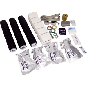
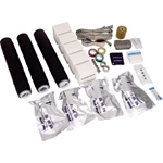
Yes, the installation process itself carries safety risks. Cold Shrink Cable Accessories remove open flames, but field records show that most failures come from workmanship errors. Incorrect shield cut-back, contaminated surfaces, and uncontrolled core removal can distort electric field stress and trigger partial discharge. The product is reliable; the installation is where risk enters.
Why Flame-Free Installation Still Has Risk
No open flame does not mean no risk. Fire hazards disappear, but risk shifts to process precision. The installer must strip the semiconductive layer accurately, position the stress cone correctly, and control support core removal speed. Any deviation changes electric field distribution and causes partial discharge. A cold shrinkable termination depends on interface pressure, not heat.
Four Installation Errors That Cause Failure
1. Shield Cut-Back and Stress Cone Misalignment
Wrong cut-back position of the semiconductive layer is a leading failure cause. When stress cone overlap is insufficient, electric field stress concentrates, and a cold shrinkable termination can break down. Overlap dimensions differ by voltage class. Measure against the kit instructions.
2. Surface Contamination and Semiconductive Residue
Dust, moisture, oil, and semiconductive residue form conductive paths. The cleaning sequence is clean, abrade, clean again. Any particle on the insulation surface becomes a partial discharge site. Surface preparation decides insulation performance more than product selection.
3. Uncontrolled Support Core Removal
Unstable pulling speed traps air bubbles at the interface. These voids become partial discharge points under voltage. Field teams sometimes call this process cool shrink because no heat is applied. Even, slow removal reduces bubble formation and protects the cable surface from digging.
4. Moisture, Dust, and Poor Work Area Control
Rain, high humidity, and dusty conditions damage sealing quality. Water ingress at the conductor lug is a documented cause of termination failure. A dry work tent and controlled environment are mandatory, not optional. Work area control directly affects service life.
Installation Risk Matrix for Cold Shrink Cable Accessories
| Risk Factor | Failure Mode | Control Measure |
|---|---|---|
| Shield cut-back error | Stress concentration | Measure per voltage class |
| Contaminated surface | Partial discharge | Clean, abrade, clean again |
| Fast core pull | Air voids | Steady, even pulling |
| Moisture exposure | Seal failure | Use dry work tent |
| Wrong kit match | Insulation breakdown | Verify voltage and cross-section |
This matrix supports safe work with Cold Shrink Cable Accessories.
Field Evidence and Standards
35 kV Terminal Breakdown at a PV Station
A 35 kV photovoltaic station experienced a cable terminal breakdown. Destructive sampling confirmed that construction and installation techniques caused the failure, not the product. The cold shrinkable joint was correctly manufactured. Workmanship was the root cause.
25 kV Electric Field Simulation
A finite element study on 25 kV cold shrinkable termination showed that knife cuts, positioning errors, and contamination alter electric field distribution. These defects reduce insulation performance and increase breakdown probability.
Step-by-Step Controls to Reduce Installation Risk
-
Verify kit-to-cable match before cutting. Check voltage class, cross-section, and shield construction.
-
Control the workspace. Keep exposed insulation clean and dry.
-
Measure shield cut-back and stress cone overlap per voltage class.
-
Clean, abrade, and clean again. Remove all semiconductive residue.
-
Pull the support core evenly. Avoid jerking or fast removal.
-
Inspect before energizing. Check wrinkles, lifted edges, and earthing.
These steps apply to cold shrinkable cable joints and terminations. A terminal strip marker carrier can support phase identification, reducing misconnection risk.
FAQ
Q: Can cold shrink accessories be installed in wet conditions?
A: No. Moisture on the insulation surface creates partial discharge sites. A dry, controlled environment is mandatory.
Q: What is the most common installation mistake?
A: Improper stress cone positioning relative to the semiconductive layer. This error is a leading cause of termination breakdown.
Q: Does installer skill affect cold shrinkable termination reliability?
A: Yes. Positioning, cleaning, and core removal speed depend on trained hands. The technology simplifies work but does not remove precision requirements.
Q: Is cool shrink the same as cold shrink?cold shrinkable cable joints
A: Cool shrink is an informal field term for the same no-heat process. The core technology remains cold shrink installation.
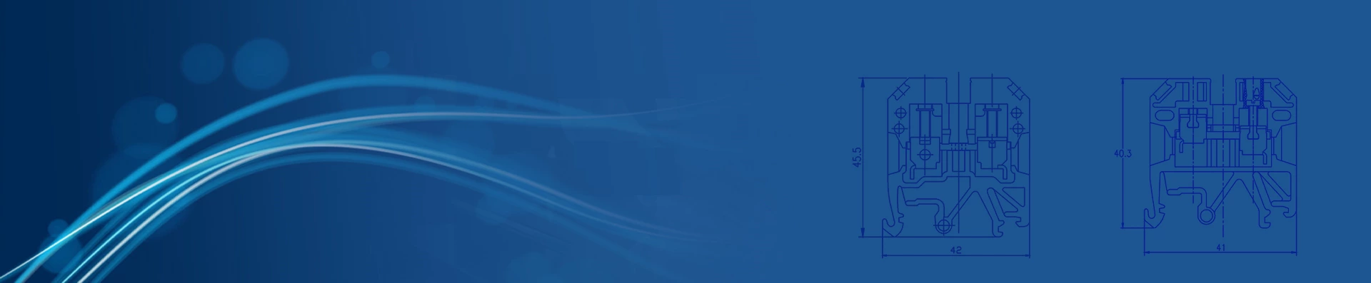
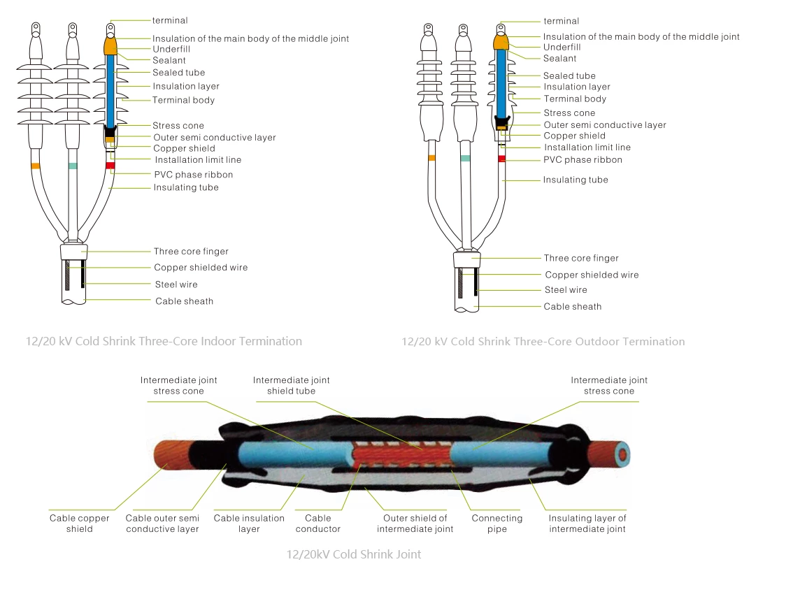
12/20, 18/20 kV Fully Cold Shrink Three-Core Terminal – Installation Outline Drawing
Electrical Performance Tests
| No. | Test Item | Standard Requirements |
| 1 | Power Frequency Withstand Voltage | 54 kV, 5 min, No Breakdown |
| 2 | Partial Discharge Test | Partial Discharge Magnitude≤ 10 pC at 20 kV |
| 3 | Impulse Voltage Test | 125 kV, 10 positive and 10 negative impulses, no breakdown |
| 4 | Constant Voltage Load Cycling Test (in Air) | 35 kV, conductor temperature 95–100 ℃, total 60 cycles, no breakdown, no flashover |
| 5 | Thermal Stability Test (185 mm² Conductor) | 23.4 kA, 2 s, twice, no visible damage |
| 6 | Dynamic Stability Test | 82.6 kA, ≥ 10 ms, no visible damage |
| 7 | Moisture Test (Indoor) | 15 kV, 300 h, no breakdown, no flashover |
| 8 | Salt Spray Test (Outdoor) | 15 kV, 1000 h, no breakdown, no flashover |
Product overview
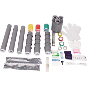
◆The product is available in single-core, two-core, three-core, four-core, and five-core versions, and has been widely used for low-voltage cable terminations and intermediate connections.
◆Excellent surface hydrophobicity, ensuring the product maintains strong resistance to contamination.
◆Compact size, lightweight, and reliable performance.
◆Application Scope: The product demonstrates excellent cold and heat resistance, making it particularly suitable for high-altitude, cold, humid, salt-spray, and heavily polluted environments.
Installation requires no open flame, making it ideal for flammable and explosive areas such as petroleum, chemical, mining, and tunneling sites.
 |
 |
 |
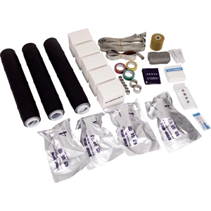 |
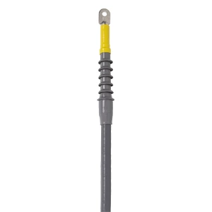
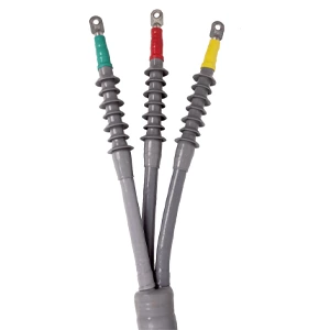
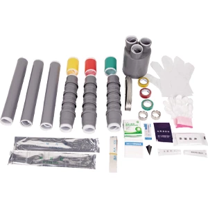
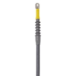
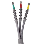
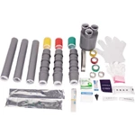
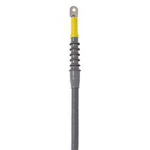
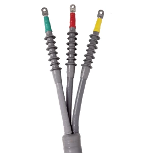
| 12/20 kV Single-Core Cold Shrink Indoor Termination – Installation Drawing | 12/20 kV Three-Core Cold Shrink Outdoor Termination – Installation Drawing | 12/20 kV Three-Core Cold Shrink Outdoor Termination – Supporting Drawing | 12/20 kV Three-Core Cold Shrink Intermediate Connection – Supporting Drawing |
Technical Data - Model Selection
| Product Type | Model | Conductor Cross-section(mm²) |
| 12/20 kV Cold Shrink Indoor Termination | GHD-20HNLS-3(1)*35-500 | 35-500 |
| 12/20 kV Cold Shrink Outdoor Termination | GHD-20HWLS-3(1)*35-500 | 35-500 |
| 12/20 kV Cold Shrink Joint | GHD-20JTLS-3(1)*35-500 | 35-500 |
| 18/20 kV Cold Shrink Indoor Terminationl | GHD-24HNLS-3(1)*35-630 | 35-630 |
| 18/20 kV Cold Shrink Outdoor Termination | GHD-24HWLS-3(1)*35-630 | 35-630 |
| 18/20 kV Cold Shrink Joint | GHD-24JTLS-3(1)*35-630 | 35-630 |
