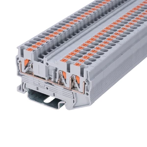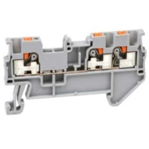
Push In Terminal Block for DIN Rail Push Fit Connections
- Type:
- Multi-conductor terminal block
- Nominal Voltage:
- 800 V
- Nominal Current:
- 32 A
- Number Of Connections:
- 3
- Connection Method:
- Push-in connection
- Rated Cross Section:
- 4 mm²
- Mounting type:
- DIN Rail (EN 60715)
- Compatible Rail:
- NS 35/7,5, NS 35/15
- Cross Section:
- 0.2 mm² - 6 mm²
- Color:
- gray
Cabinet wiring demands rapid assembly, zero maintenance, and stable conductivity under constant mechanical shock. Traditional screw clamps risk wire loosening over time, increasing cabinet downtime. The modern solution relies on Push-In Type Terminal Blocks, which eliminate screw torque verification while accelerating installation speeds up to 50%.
Streamlined Enclosure Assembly with Push Fit Technology
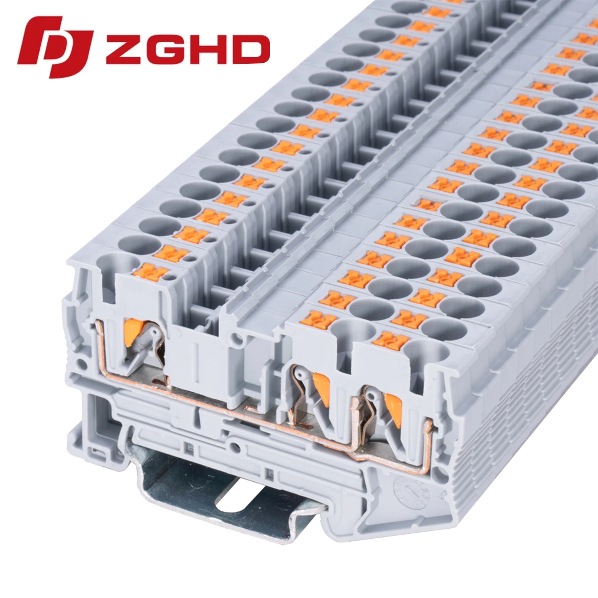
Inserting solid or ferrule-ended conductors directly into a push in terminal block requires zero tools. A calibrated stainless steel leg spring clamps the conductor firmly against a tinned electrolytic copper current bar, ensuring low contact resistance and gas-tight electrical contact.
Operational Advantages in High-Vibration Environments
-
Tool-Free Conductor Entry: Stripped wires push directly into push fit din rail terminals, locking instantly without retightening routines.
-
Vibration-Proof Clamping: Constant spring pressure resists heavy industrial transit shock, preventing arcing.
-
Orange Disconnect Actuator: Integrated push buttons release conductors smoothly without surface contact with live elements.
Engineering Reliability with Hangda Electrical
Hangda Electrical manufactures the JHD1.4-1/2 Feed-Through Terminal Block, engineered to meet strict international standards on standard TS 35 mounting tracks. Selecting a robust push fit terminal block guarantees flame-retardant performance under extreme operating temperatures.
Technical Specifications
| Parameter | Specification |
|---|---|
| Model Reference | JHD1.4-1/2 |
| Manufacturer | Hangda Electrical |
| Mounting Type | DIN Rail TS 35 / TS 32 |
| Rated Voltage / Current | 800 V / 24 A |
| Cross Section Range | 0.2 mm² – 2.5 mm² |
| Housing Material | Polyamide PA66 (UL 94 V-0) |
| Stripping Length | 10 mm |
Recommended Installation Procedure
-
Strip conductor insulation cleanly to the specified insertion depth.
-
Push the wire straight into the designated push in type terminal block wire aperture.
-
Verify mechanical retention with a gentle tug test before closing the cabinet.
| Wiring Diagram | 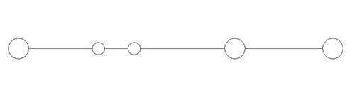 |
| Thickness/Witdh/Height | 6.2*66.8*35.5 mm |
| Nominal cross section | 4 mm² |
| Rated current | 32 A |
| Rated voltage | 800 V |
| Color | Grey |
| Insulating material | PA66 |
| Flame retardant rating UL-94 | V0 |
| Connection type | Push in |
| The minimum cross section(Rigid wire) | 0.2 mm² |
| The maximum cross section(Rigid wire) | 6 mm² |
| The minimum cross section(Soft wire) | 0.2 mm² |
| The maximum cross section(Soft wire) | 4 mm² |
| Cover | ST2-4/1X2G |
| Jumper | UFB 10-6 |
| Marker | ZB6M |
| Dimensions | 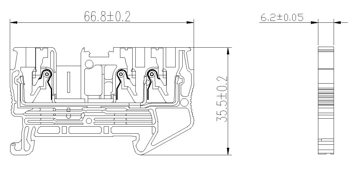 |