6mm Multi-level Terminal Blocks: How A Compact Footprint Completes Three-phase Motor Wiring
- Type:
- Double-level terminal block
- Nominal Voltage:
- 500 V
- Nominal Current:
- 32 A
- Connection Method:
- Screw connection, 1st and 2nd level
- Rated Cross Section:
- 4 mm²
- Cross Section:
- 0.2 mm² - 4 mm²
- Color:
- gray
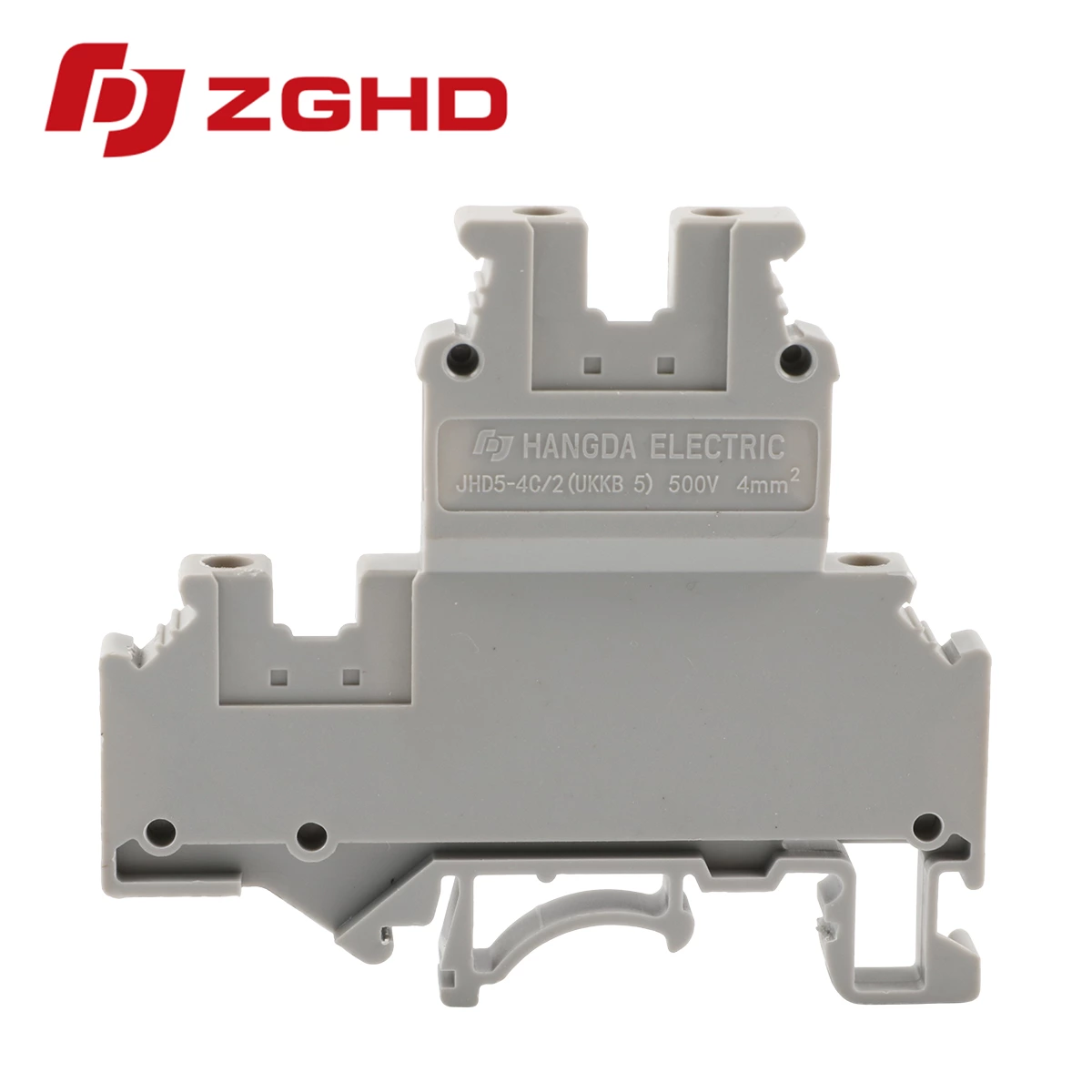
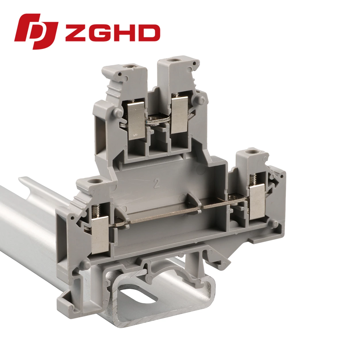
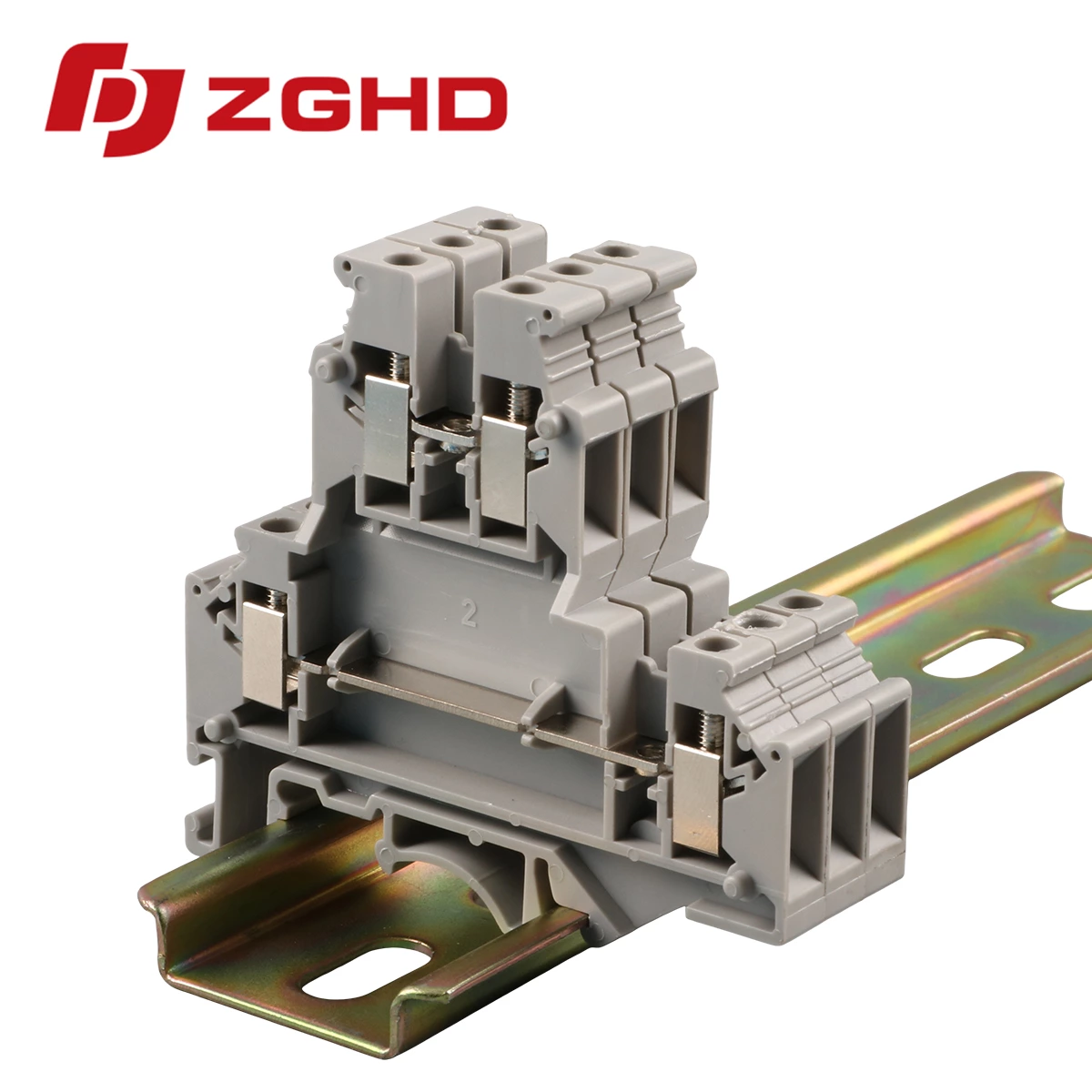
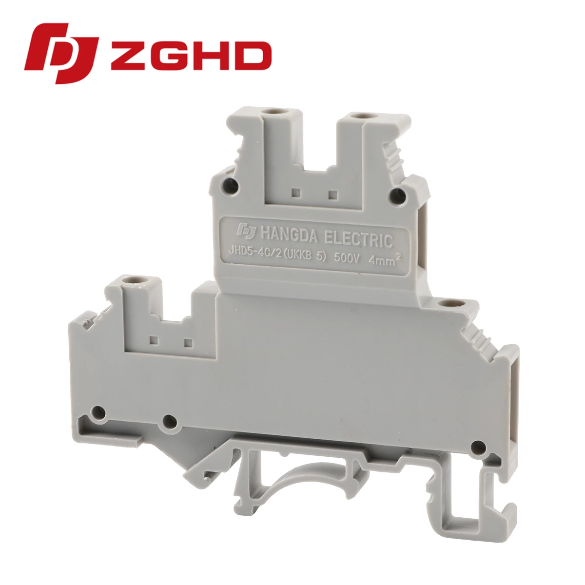
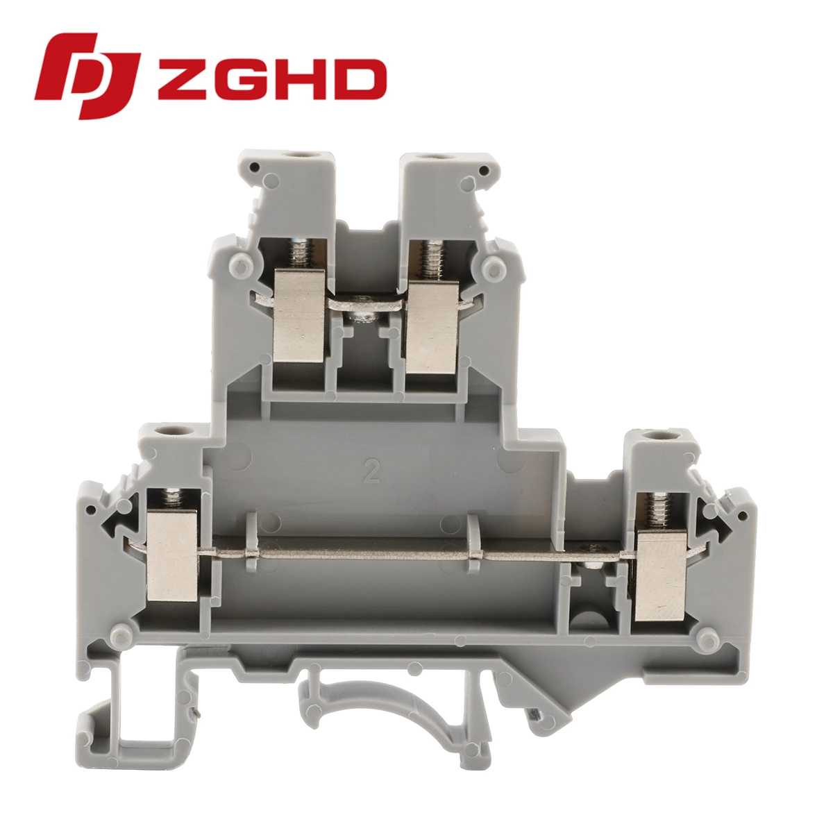
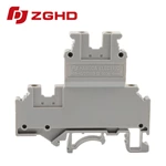
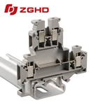
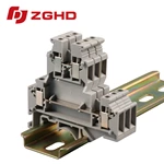
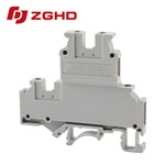
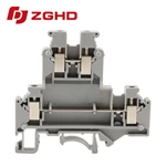
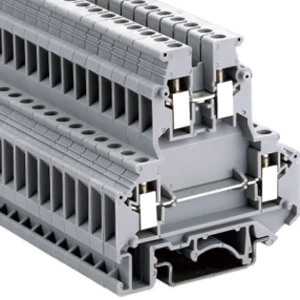
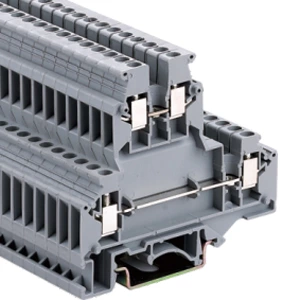
A 6mm multi-level terminal block terminates three motor phases plus a protective conductor in one housing. The unit stacks four circuits vertically within a 6mm pitch, rated 32A at 500V AC with 4mm² cross-section. Compared with four separate single-level blocks, it cuts DIN rail occupation by roughly 75%. This layout suits compact control cabinets, OEM machine panels, and motor feeder circuits where rail length runs short. The block accepts rigid and flexible copper conductors, mounts on 35mm DIN rail, and carries an IP20 protection degree.
What the Block Does in a Motor Feeder
Three Phases and PE in One Housing
The stacked design places L1, L2, and L3 on separate levels. A PE foot contacts the mounting rail directly. Phase bridges replace external jumpers between blocks.
Ratings to Verify
| Parameter | Value | Reference |
|---|---|---|
| Pitch width | 6mm | Datasheet |
| Rated cross-section | 4mm² | IEC 60947-7-1 |
| Rated current | 32A | UL 1059 |
| Rated voltage | 500V AC | IEC 60947-7-1 |
| Protection degree | IP20 | IEC 60529 |
Why Rail Space Matters
A conventional layout needs four positions per motor: three phases plus ground. Each position adds rail length, jumper wiring, and misconnection points.
A multi level terminal blocks layout consolidates all four terminations at one point. On a 200mm rail, motor circuit count rises from eight to roughly thirty-two.
Benefits include:
-
🔧 Fewer jumper wires between blocks
-
📉 Lower risk of wiring errors during assembly
-
📏 More horizontal rail space for contactors and relays
-
⚡ Shorter conductor runs inside the enclosure
Wiring Steps for a Three-Phase Motor
-
Confirm motor full-load amps sit below the 32A rating.
-
Strip conductors to 8–10mm, per the specification sheet.
-
Insert L1, L2, L3 into the upper levels; place PE in the PE level.
-
Tighten screws to 0.6–0.8 N·m.
-
Install the phase bridge to feed downstream devices.
-
Test each level through the function shaft without removing conductors.
-
Verify PE continuity between the terminal and the rail.
Selecting the Right Unit
Current, Voltage, and Cross-Section
Motor full-load amps must not exceed 32A. Both rigid and flexible 4mm² wire fit the clamp. Ferrules are advised for flexible conductors to stop strand fanning.
PE and Grounding
A PE foot contacting the rail removes the need for a separate grounding terminal. The connection must remain low-resistance and independent of phase bridges.
Accessory Compatibility
Check that phase bridges, marker strips, and test probes match the chosen multi level terminal. Confirm 35mm DIN rail mounting before ordering.
Selection checklist:
-
Current rating ≥ motor full-load amps
-
Voltage rating ≥ system voltage plus margin
-
Cross-section range covers installed wire
-
PE type suits the grounding scheme
-
Bridges available for phase distribution
Vibration and Fault Conditions
Self-Locking Screw Mechanism
Motor circuits run under continuous vibration. A self-locking screw mechanism maintains clamping force, preventing loosening that leads to resistance heating.
Thermal Derating
Side-by-side mounting raises ambient temperature around the block. Reduce current accordingly, following the derating curve in the specification sheet. The terminal does not replace upstream breakers or contactors.
| Failure Mode | Cause | Prevention |
|---|---|---|
| Screw loosening | Vibration | Self-locking mechanism |
| Overheating | Loose joint or overload | Torque check, derating |
| PE discontinuity | Poor rail contact | PE foot inspection |
| Bridge mismatch | Wrong accessory | Verify compatibility |
Common Questions
Q: Can a 6mm block carry 32A continuously?
A: Derate for ambient temperature and adjacent blocks; consult the specification sheet.
Q: Does it accept 4mm² flexible wire?
A: Yes, with ferrules recommended.
Q: Is a separate PE terminal needed?
A: Not when the block has a PE foot in solid rail contact.
Q: How many motor circuits fit on 200mm of rail?
A: One circuit occupies one 6mm position, so about thirty-two, minus spacing margin.
Q: Does it meet IEC 60947-7-1?
A: Confirm the certificate for the exact model before claiming compliance.
| Model | Function | Wire IEC cross-section | Wire UL | Thickness | Maximum current | Number of packages | Thickness/Height( )/Width mm )/Width mm |
Rated voltage/rated current/rated cross-sectior |
| JHD5-4C/2 | 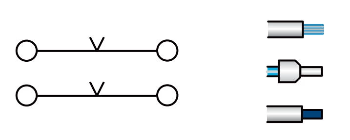 |
4 mm² 2.5 mm² 4 mm² |
12 AWG 14 AWG 12 AWG | 6.2 mm | 32 A | 100 | 6.2/62/67 | 500 V/32 A/4 mm² |
Specfication:
| End cover | D2.5C/2 |
| Cross-connection 10-Polo,Separable | ZL2-4 ZL3-4 ZL10-4 |
| Insertion bridge 10-Polo,Separable | BLS2-4 BLS3-4 BLS10-4 |
| Small Partition | CPK3 |
| Marking tags | ZB6 |
| Screw/Tightening torque(Nm) | M3/0.6 |
| Material | PA |
| Flame retardant rating UL-94 | V0 |
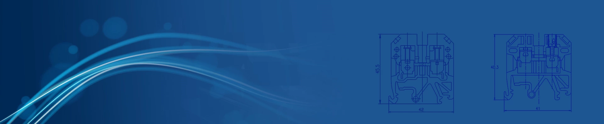
| Dimensions | 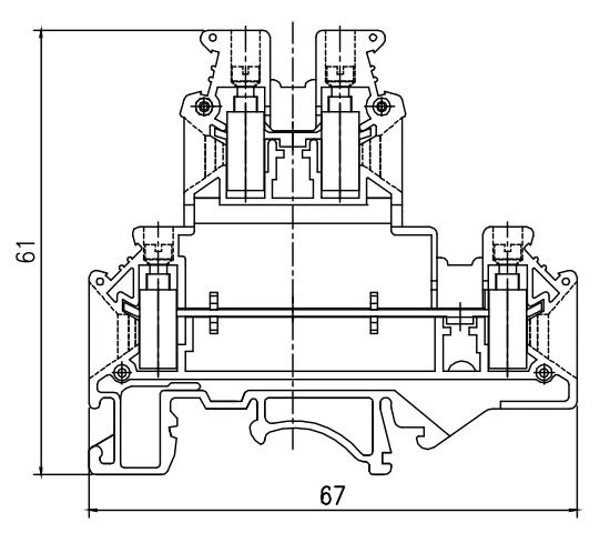 |
With universal mounting feet for standard top-hat(Ω profile) and G-profile DIN rail mounting.