Screened Separable Connectors Insulated Cable Types Guide
- Rated voltage:
- 35 kV
- Rated current:
- 630 A
- AC Withstand Voltage for 5min:
- 117 kV
- Partial Discharge:
- 45 kV,≤10 pC
- Impulse Withstand Voltage(10 times foreach polarity):
- 200 kV
- Screen Resistance:
- ≤5000 Ω
- Reference standards:
- GB/T 12706.4、IEC 60502-4

Standardizing medium-voltage terminations often reveals mismatched cable diameters and premature insulation breakdown inside compact switchgear compartments. Screened separable connectors eliminate these interface headaches across diverse solid-dielectric cable installations.
Cable Compatibility Matrix
Modern distribution networks rely on two dominant polymeric insulation profiles:
-
Cross-linked polyethylene (XLPE): Rigid thermal tolerance, requiring precise stress cone expansion.
-
Ethylene propylene rubber (EPR): Flexible jacket geometry, ideal for tight cabinet bends.
Whether terminating single-core aluminum or three-core armored copper conductors, each separable cable connector must match the outer insulation diameter rather than nominal conductor size alone.
Performance Benchmark: Hangda Electric 630A Solution
Rated up to 40.5 kV, the 26/35 kV 630A front plug-in cable connector from Hangda Electric provides an EPDM-molded, fully submersible barrier for CENELEC EN 50181 Type C bushings.
| Parameter | Rating |
|---|---|
| System Voltage | 26/35 kV (Max 40.5 kV) |
| Continuous Current | 630 A |
| AC Withstand (5 min) | 117 kV |
| Partial Discharge Threshold | ≤ 10 pC at 45 kV |
| Basic Impulse Insulation (BIL) | 200 kV |
Practical Field Advantages
Site teams installing Separable Insulated Connectors benefit from specific design refinements:
-
Conductive EPDM shielding maintains touch-safe outer jacket potential without supplemental grounding tape.
-
Integrated capacitive test sockets allow immediate de-energization checks before unbolting.
-
Cold-applied stress geometry accommodates cross-sections from 35 mm² through 500 mm².
Specifying the correct Separable Connector resolves flashover vulnerabilities across renewable feeder circuits. Hangda Electric supplies factory-tested Separable Connectors built to keep regional distribution assets operating without unexpected outages.
Product features
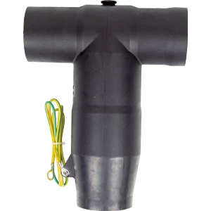
The 630 A front plug-in cable connector directly connects to the incoming and outgoing bushings of switchgear and the bushings of cable branch boxes, providing fully insulated and safe circuits for switchgear and cable branch boxes.
During front plug-in operation, it is bolted to the switchgear bushing seat; the rear end can be directly sealed with an insulator or extended to connect to a rear connector arrester. Utilizing advanced post-injection technology, the outer layer has a semi-conductive layer that acts as a shield, is touch-safe, and ensures personal safety. The unique stress cone structure effectively disperses electric field stress and addresses electric field stress issues at the cut-off point of the cable shielding layer. It offers expandability, flexible disassembly, and assembly, enabling T-type cable connections, and is fully sealed, fully insulated, fully protected, maintenance-free, submersible-resistant, and pollution-resistant.

Technical Data
| Rated voltage | 35 kV | ||
| Rated current | 630 A | ||
| AC Withstand Voltage for 5min | 117 kV | ||
| Partial Discharge | 45 kV,≤10 pC | ||
| Impulse Withstand Voltage(10 times foreach polarity) | 200 kV | ||
| Screen Resistance | ≤5000 Ω | ||
| Reference standards:GB/T 12706.4、IEC 60502-4 | |||
Models Selection
| Product model | Cross sectional area nominal(mm²) | 26/35 kV voltage level cable insulation outer diamerer(mm²) | ||
| GHD-35/630A-QC-35 | 35 | 29 | ||
| GHD-35/630A-QC-50 | 50 | 31 | ||
| GHD-35/630A-QC-70 | 70 | 32.6 | ||
| GHD-35/630A-QC-95 | 95 | 34.2 | ||
| GHD-35/630A-QC-120 | 120 | 35.6 | ||
| GHD-35/630A-QC-150 | 150 | 37.2 | ||
| GHD-35/630A-QC-185 | 185 | 38.7 | ||
| GHD-35/630A-QC-240 | 240 | 41.1 | ||
| GHD-35/630A-QC-300 | 300 | 43.2 | ||
| GHD-35/630A-QC-400 | 400 | 46.6 | ||
| GHD-35/630A-QC-500 | 500 | 49.2 | ||
Product accessory Illustration


