Separable Connector Contact Design: Why Application Dictates The Answer
- Rated voltage:
- 15 kV
- Rated current:
- 630 A
- AC Withstand Voltage for 5min:
- 39 kV
- Partial Discharge:
- 15 kV,Q≤10 pC
- Impulse Withstand Voltage(10 times foreach polarity):
- 95 kV
- Screen Resistance:
- ≤5000 Ω
- Reference standards:
- GB/T 12706.4、IEC 60502-4
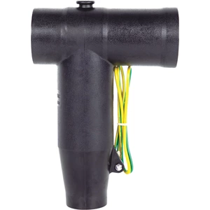
A separable connector’s elastic contact must match its application. Marine designs prioritize corrosion and partial discharge control. Electric vehicle designs prioritize vibration retention and thermal cycling. Aerospace and industrial designs follow shock, vacuum, EMI, and washdown demands. Contact force, sealing, and material selection follow the dominant failure mode.
Application Determines Contact Structure
Marine: corrosion and partial discharge. EV: vibration, thermal cycling, and high-voltage interlock. Aerospace: launch shock, thermal vacuum, blind mate. Industrial: EMI and washdown. A separable connector succeeds only when spring force, wipe distance, and plating match the primary degradation driver.
Marine Engineering: Seawater, Pressure, and Sacrificial Separation
Failure Modes in Subsea Environments
Chloride corrosion, hydrostatic pressure, insulation aging, and partial discharge dominate. Submerged equipment must hold insulation integrity without maintenance access.
Contact and Insulation Requirements
A stress cone disperses electric field stress at the shielding cut-off. Partial discharge ≤10 pC at 15 kV prevents insulation degradation. Salt spray and immersion certifications confirm material performance.
Certified Performance Example
A 15 kV, 630 A front plug-in connector rated for submersible service shows the baseline. Its stress cone structure and metallic encapsulation support touch-safe operation. Shear-pin breakaway mechanisms sacrifice the connector to protect the cable assembly.
Selection Checklist for Offshore Projects
-
Depth and pressure rating
-
Corrosion protection
-
Partial discharge limit
-
Sacrificial separation design
Electric Vehicles: Vibration, Thermal Cycling, and HVIL
Degradation Drivers in EV Powertrains
Road input and drivetrain harmonics create 20 g acceleration events. Thermal cycling spans -40°C to +125°C. Road spray and washdown demand IP6K9K sealing.
Contact Force vs. Serviceability
A 12 mm contact rated to 450 A and 2,000 Vdc must hold low resistance through 500 mating cycles. High contact force prevents vibration loosening but slows assembly and maintenance.
Sealing and Interlock Integration
High-voltage interlock signals incomplete mating, preventing arc exposure. Sealing geometry must not interfere with the elastic contact’s deflection range.
EV Connector Selection Checklist
-
Vibration retention
-
Temperature rise and current
-
Sealing class
-
Interlock logic
Industrial Control and Aerospace: Different Constraints, Different Compromises
Industrial: EMI, Washdown, Signal Integrity
Screened separable connectors with ≤3 mΩ contact resistance and IP67 protection serve factory automation. The elastic contact must survive millions of low-current cycles.
Aerospace: Shock, Thermal Vacuum, Blind Mate
Launch shock and thermal vacuum demand controlled separation. Separable insulated connectors allow blind-mate operation in confined spaces. A separable cable connector here may use assisted separation force without direct access.
Comparison Table: Application vs. Degradation Driver vs. Contact Priority vs. Sealing
| Application | Primary Driver | Contact Force | Sealing |
|---|---|---|---|
| Marine | Corrosion + PD | Moderate, stable | Submersible |
| EV | Vibration + thermal | High retention | IP6K9K + HVIL |
| Aerospace | Shock + vacuum | Controlled separation | Hermetic |
| Industrial | EMI + washdown | Low resistance | IP65–IP67 |
How to Select a Separable Connector: 5-Step Framework
-
Define primary failure mode
-
Set contact force range
-
Confirm sealing and IP rating
-
Check IEC and DNV GL standards
-
Verify serviceability and interlock needs
Product Integration and Next Step
View the 15 kV 630 A front plug-in connector, download the product specification sheet, or request a quote. Separable Connectors for offshore wind and EV powertrains share insulation materials but use different spring geometry. The contact wipe that cleans oxides in a dusty enclosure becomes an abrasion risk in a clean-environment connector.
FAQ
Q: What is a separable connector?
A: A separable connector allows mating and unmating under load without permanent splicing. Its elastic contact maintains force across thermal and mechanical cycles.
Q: When should screened separable connectors be used?
A: Screened separable connectors suit industrial control and factory automation where EMI and washdown coexist.
Q: How do separable insulated connectors differ from separable cable connectors?
A: Separable insulated connectors emphasize insulation integrity for power distribution. Separable cable connectors may prioritize mechanical retention and separation force for specific cable assemblies.
Product features
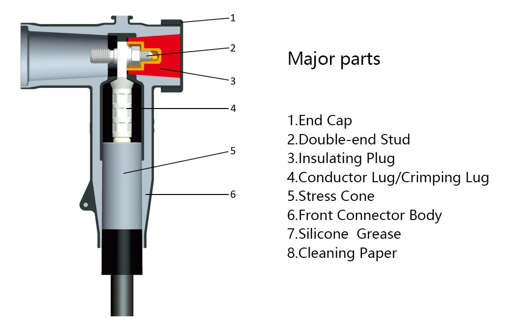
The 630 A front plug-in cable connector directly connects to the incoming and outgoing bushings of switchgear and the bushings of cable branch boxes, providing fully insulated and safe circuits for switchgear and cable branch boxes.
During front plug-in operation, it is bolted to the switchgear bushing seat; the rear end can be directly sealed with an insulator or extended to connect to a rear connector arrester. Utilizing advanced post-injection technology, the outer layer has a semi-conductive layer that acts as a shield, is touch-safe, and ensures personal safety. The unique stress cone structure effectively disperses electric field stress and addresses electric field stress issues at the cut-off point of the cable shielding layer. It offers expandability, flexible disassembly, and assembly, enabling T-type cable connections, and is fully sealed, fully insulated, fully protected, maintenance-free, submersible-resistant, and pollution-resistant.
The product complies with the C-type bushing design standards in EN50180 and EN50181.
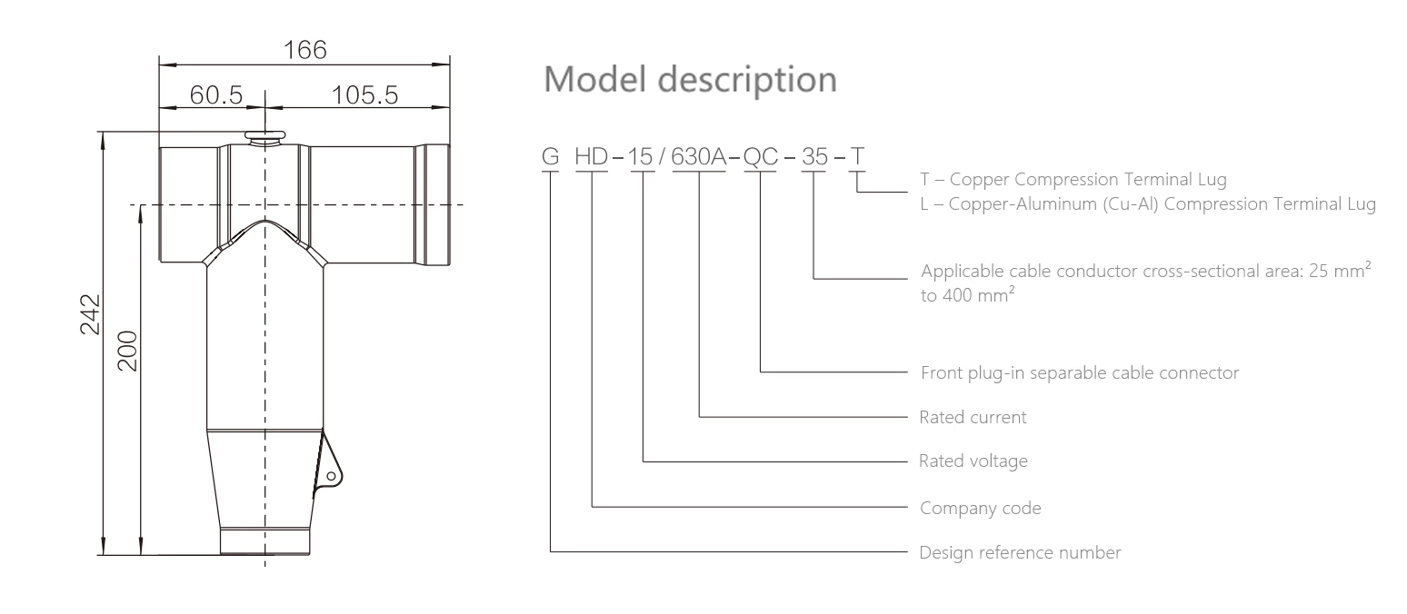
Technical Data
| Rated voltage | 15 kV |
| Rated current | 630 A |
| AC withstand voltage (5 min) | 39 kV |
| Partial Discharge | 15 kV,Q≤10 pC |
| Impulse withstand voltage (± polarity, 10 impulses each)) | 95 kV |
| Screen Resistance | ≤5000 Ω |
| Reference standards:GB/T 12706.4、IEC 60502-4 | |
Models Selection
| Product model | Nominal Cross Sectional(mm²) | 8.7/15 kV Outer Diameter of Cable Insulation(mm²) |
| GHD-15/630A-QC-25 | 25 | 16.6 |
| GHD-15/630A-QC-35 | 35 | 17.6 |
| GHD-15/630A-QC-50 | 50 | 19 |
| GHD-15/630A-QC-70 | 70 | 20.6 |
| GHD-15/630A-QC-95 | 95 | 22.2 |
| GHD-15/630A-QC-120 | 120 | 23.6 |
| GHD-15/630A-QC-150 | 150 | 25.2 |
| GHD-15/630A-QC-185 | 185 | 26.7 |
| GHD-15/630A-QC-240 | 240 | 29 |
| GHD-15/630A-QC-300 | 300 | 31.2 |
| GHD-15/630A-QC-400 | 400 | 34.4 |
| GHD-15/630A-QC-500 | 500 | 38 |
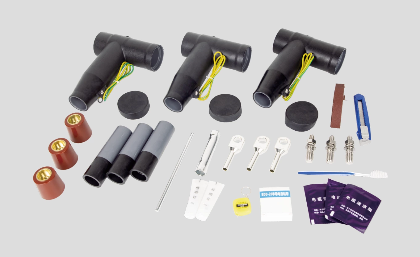
Product accessory Illustration