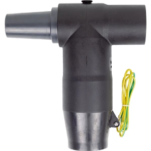
Screened Insulated Cable Separable Connector Solutions
- Rated voltage:
- 15 kV
- Rated current:
- 630 A
- AC Withstand Voltage for 5min:
- 39 kV
- Partial Discharge:
- 15 kV,Q≤10 pC
- Impulse Withstand Voltage(10 times foreach polarity):
- 95 kV
- Screen Resistance:
- ≤5000 Ω
- Reference standards:
- GB/T 12706.4、IEC 60502-4


Medium-Voltage Termination Design and Reliability
Modern compact switchgear and ring main units require high electrical integrity within limited cabinet space. Premium Separable Connectors resolve flashover risks and mechanical stress at cable termination junctions. Fabricated from peroxide-cured EPDM rubber, these units provide continuous insulation screening, suppress partial discharge, and shield terminations against moisture, dust, and environmental contamination.
Performance Advantages in Substation Applications
Multi-Circuit Expansion Capabilities
Operating medium-voltage networks demands flexibility during power distribution retrofits. Screened separable connectors allow direct coupling to standard EN 50181 Type C bushings. The outer conductive layer remains fully touch-proof during energized conditions, ensuring safe routine maintenance checks.
Separable insulated connectors provide distinct operational benefits across underground distribution networks:
-
Submersible IP67 protection suitable for flooded underground vaults.
-
Built-in capacitive test points for rapid phase checking and voltage detection.
-
Rear-mount stacking architecture allowing dual-cable circuits without expanding switchgear dimensions.
Technical Specifications
| Parameter | Specification |
|---|---|
| Rated Voltage | 8.7/15 kV |
| Continuous Current | 630 A |
| Bushing Standard | EN 50181 Interface C |
| Conductor Range | 35 – 400 mm² |
| Material Formulation | Peroxide-cured EPDM |
| Dielectric Test | 39 kV / 5 min |
Selection and Operational Checklist
System operators select cable accessories based on conductor cross-section, insulation outer diameter, and load capacity. Choosing an appropriate Separable Connector ensures tight mechanical tolerance with mating switchgear bushings.
When ordering a separable cable connector, verify the following parameters:
-
Confirm system voltage levels and continuous current requirements.
-
Measure conductor material compatibility for copper or aluminum shear-bolt lugs.
-
Validate surge arrester compatibility for direct rear-stacking configurations.
Direct consultation ensures tailored insulation thickness and optimized installation kits for specific network configurations.
Product features
The 630 A rear plug-in cable connector is used in conjunction with the front plug-in cable connector product. It provides branching for 630 A circuits but cannot be directly connected to products such as bushings. Its rear end can be sealed with an insulator or extended to connect another rear plug-in cable connector and rear plug-in arrester.
Utilizing advanced rear injection technology, the outer layer features a semi-conductive shielding layer that is touch-safe, ensuring personal safety. The unique stress cone structure effectively dissipates electric field stress, resolving electric field stress issues at the cut-off point of the cable shielding layer. It offers expandability, flexible installation and removal, and enables T-type cable connections. The product is fully sealed, fully insulated, fully protected, maintenance-free, submersible-resistant, and pollution-resistant.

Technical Data
| Rated voltage | 15 kV | ||
| Rated current | 630 A | ||
| AC withstand voltage (5 min) | 39 kV | ||
| Partial Discharge | 15 kV,Q≤10 pC | ||
| Impulse withstand voltage (± polarity, 10 impulses each) | 95 kV | ||
| Screen Resistance | ≤5000 Ω | ||
| Reference standards:GB/T 12706.4、IEC 60502-4 | |||
Models Selection
| Product model | Cross sectional area nominal(mm²) | 8.7/15 kV Outer Diameter of Cable Insulation(mm²) | ||
| GHD-15/630A-HC-25 | 25 | 16.6 | ||
| GHD-15/630A-HC-35 | 35 | 17.6 | ||
| GHD-15/630A-HC-50 | 50 | 19 | ||
| GHD-15/630A-HC-70 | 70 | 20.6 | ||
| GHD-15/630A-HC-95 | 95 | 22.2 | ||
| GHD-15/630A-HC-120 | 120 | 23.6 | ||
| GHD-15/630A-HC-150 | 150 | 25.2 | ||
| GHD-15/630A-HC-185 | 185 | 26.7 | ||
| GHD-15/630A-HC-240 | 240 | 29 | ||
| GHD-15/630A-HC-300 | 300 | 31.2 | ||
| GHD-15/630A-HC-400 | 400 | 34.4 | ||
| GHD-15/630A-HC-500 | 500 | 38 | ||
Product accessory Illustration