Quality Screened Insulated Separable Cable Connectors
- Rated voltage:
- 18/20 kV
- Rated current:
- 630 A
- AC Withstand Voltage for 5min:
- 81 kV
- Partial Discharge:
- 30 kV,Q≤10 pC
- Impulse Withstand Voltage(10 times foreach polarity):
- 170 kV
- Screen Resistance:
- ≤5000 Ω
- Reference standards:
- GB/T 12706.4、IEC 60502-4
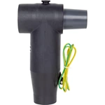
Medium-voltage power distribution requires reliable cable terminations capable of operating under confined switchgear enclosures. Screened separable connectors provide a fully shielded, submersible interface between polymeric cables and gas-insulated equipment. The grounded conductive layer ensures zero electrical clearance requirements between phases, preventing flashover risks during continuous operation.
Operational Advantages in Medium-Voltage Networks
Integrating a reliable Separable Connector into ring main units resolves spatial constraints while maintaining operational safety:
-
Touch-Proof Security: Thick outer conductive EPDM screening directs capacitive currents to ground, preventing accidental shock.
-
Dielectric Integrity: Precision-molded peroxide-cured insulation prevents partial discharge below 10 pC at elevated operating voltages.
-
Modular Expansion: Rear-fitting profiles accommodate dual-branch circuits directly behind base plugs.
Core Electrical and Mechanical Ratings
| Parameter | Specified Value |
|---|---|
| Nominal Voltage Rating | 12/20 kV (Um 24 kV) |
| Continuous Current Rating | 630 A |
| Bushing Interface Standard | EN 50181 Interface C |
| Dynamic Short-Circuit Peak | 65 kA |
Implementation and System Configuration
Modern substations deploy Separable Connectors to streamline circuit extensions without cabinet reconfiguration. Equipment upgrades benefit from specific execution steps:
-
Cable Preparation: Proper stripping maintains correct stress cone placement over the semi-conductive screen.
-
Rear Coupling: Securing a rear plug-in separable cable connector allows parallel circuit expansion on identical 630A bushings.
Separable insulated connectors maintain system continuity across heavy-duty industrial and utility networks. Explore verified configurations to secure switchgear installations today.
Product features
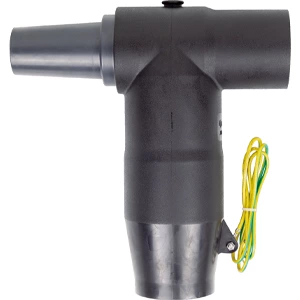
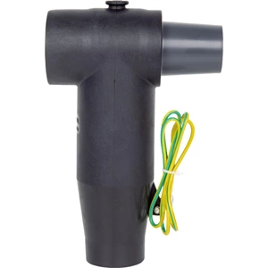
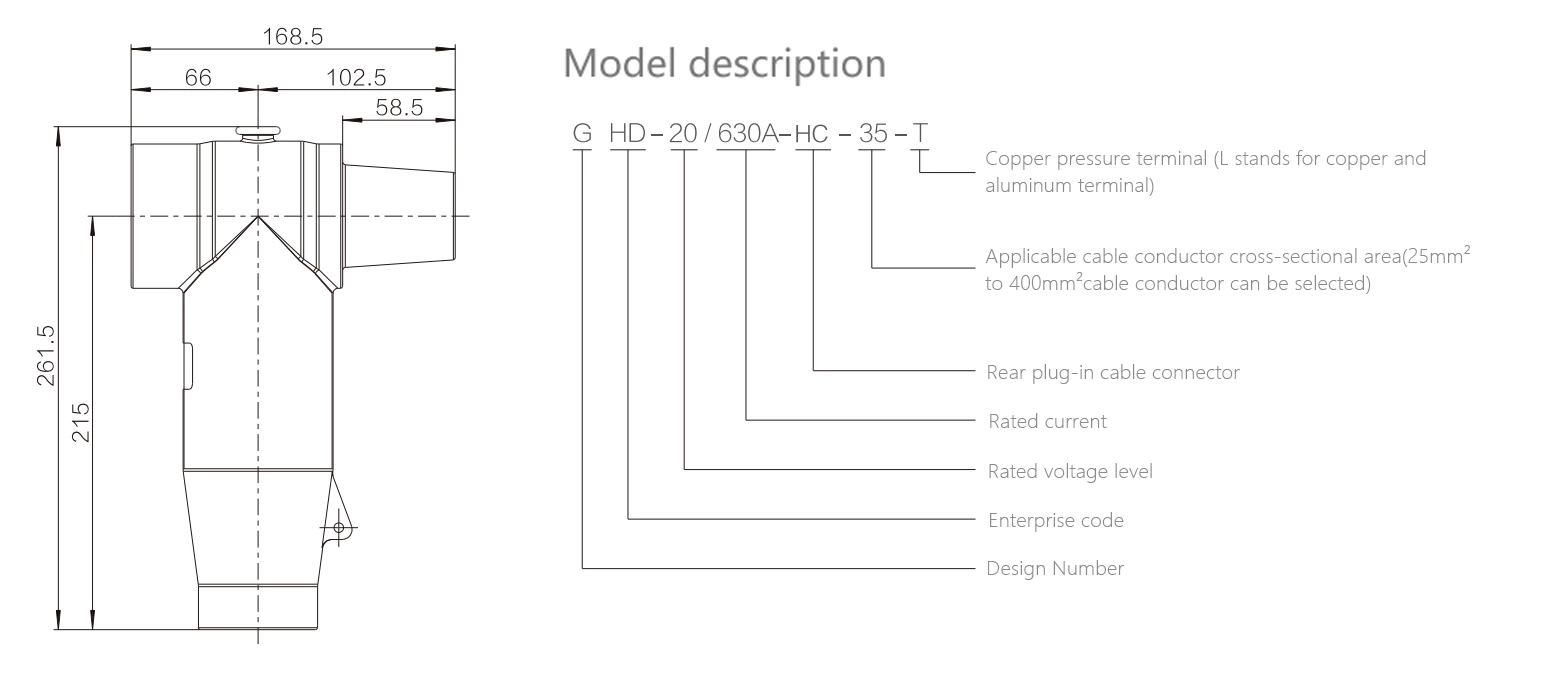
The 630 A rear plug-in cable connector is used in conjunction with the front plug-in cable connector product. It provides branching for 630 A circuits but cannot be directly connected to products such as bushings. Its rear end can be sealed with an insulator or extended to connect another rear plug-in cable connector and rear plug-in arrester.
Utilizing advanced rear injection technology, the outer layer features a semi-conductive shielding layer that is touch-safe, ensuring personal safety. The unique stress cone structure effectively dissipates electric field stress, resolving electric field stress issues at the cut-off point of the cable shielding layer. It offers expandability, flexible installation and removal, and enables T-type cable connections. The product is fully sealed, fully insulated, fully protected, maintenance-free, submersible-resistant, and pollution-resistant.
Technical Data
| Rated voltage | 18/20 kV | ||
| Rated current | 630 A | ||
| AC Withstand Voltage for 5min | 81 kV | ||
| Partial Discharge | 30 kV,Q≤10 pC | ||
| Impulse Withstand Voltage(10 times foreach polarity) | 170 kV | ||
| Screen Resistance | ≤5000 Ω | ||
| Reference standards:GB/T 12706.4、IEC 60502-4 | |||
Models Selection
| Product model | Cross sectional area nominal(mm²) | 18/20 kV voltage level cable insulation outer diamerer(mm²) | |||
| GHD-24/630A-HC-35 | 35 | 24 | |||
| GHD-24/630A-HC-50 | 50 | 25.9 | |||
| GHD-24/630A-HC-70 | 70 | 27.4 | |||
| GHD-24/630A-HC-95 | 95 | 29.1 | |||
| GHD-24/630A-HC-120 | 120 | 30.5 | |||
| GHD-24/630A-HC-150 | 150 | 32.1 | |||
| GHD-24/630A-HC-185 | 185 | 33.6 | |||
| GHD-24/630A+C-240 | 240 | 35.9 | |||
| GHD-24/630A-HC-300 | 300 | 38.1 | |||
| GHD-24/630A-HC-400 | 400 | 41.6 | |||
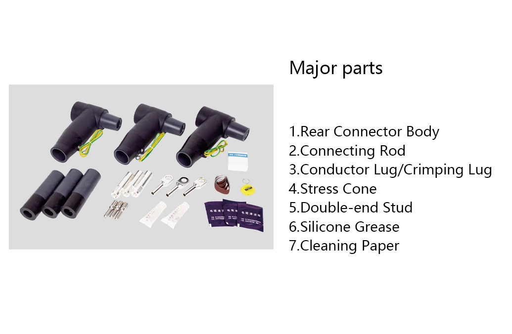
Product accessory Illustration