TDR & Eye Diagram Testing for Separable Connector Interfaces
- Rated voltage:
- 18/20 kV
- Rated current:
- 630 A
- AC Withstand Voltage for 5min:
- 81 kV
- Partial Discharge:
- 30 kV,Q≤10 pC
- Impulse Withstand Voltage(10 times foreach polarity):
- 170 kV
- Screen Resistance:
- ≤5000 Ω
- Reference standards:
- GB/T 12706.4、IEC 60502-4
Time-domain reflectometry (TDR) transmits a pulse and measures reflected energy return time to locate impedance anomalies at a separable connector interface. Eye diagram testing converts reflections and losses into eye height and width changes. Comparing fully mated and separated states quantifies signal degradation.
TDR Locates Impedance Discontinuities at Mating Interfaces
Measurement Principle
A TDR instrument launches a fast pulse into the signal path. Any impedance change produces a reflection. The return time indicates position; reflection amplitude indicates severity. This method distinguishes TDR from frequency-domain tools because it pinpoints where a problem occurs.
Fully Mated vs. Functionally Separated States
A controlled test compared a fully pressed connection with a 2 mm separation within the functional mating range. The mated state showed a 7 Ohm impedance dip. Separation produced a 5 Ohm spike. The total change reached 12 Ohms. Such values reveal how separation alters signal behavior.
Eye Diagram Analysis Quantifies Transmission Quality
Eye Height and Width Changes
A wide eye opening with low jitter indicates a healthy interface. As a separable cable connector separates, reflections increase. The eye closes vertically and horizontally. At 10 Gbps, acceptable eye height above 70% may fall to 40–55% after separation.
Multi-Rate Test Points
Screened separable connectors require evaluation at multiple speeds. Test reports often cover 5, 10, 20, and 28 Gbps. Higher rates show greater eye closure for the same separation distance. This multi-rate approach identifies the threshold where performance becomes unacceptable.
Frequency-Domain Parameters: Insertion Loss and Return Loss
| Test Parameter | Mated Condition | Separated Condition | Domain |
|---|---|---|---|
| Insertion Loss @100 MHz | ≤0.15 dB | ≤0.35 dB | Frequency |
| Return Loss @100 MHz | ≥26 dB | ≥18 dB | Frequency |
| Impedance Deviation | ±3 Ω | ±8–12 Ω | Time |
| Eye Height @10 Gbps | >70% | 40–55% | Time |
| Eye Width @10 Gbps | >80% | 50–65% | Time |
Interpreting Results
Insertion loss rises with separation due to added reflections and dielectric discontinuities. Return loss falls as more energy reflects toward the source. For separable insulated connectors in medium-voltage use, return loss above 18 dB at the highest operating frequency is a practical threshold.
Standards and Test Methods: IEC 60512-28-100:2024
Frequency Range Change
The third edition covers 0.1 MHz to 2,000 MHz. The low-frequency start extends from 1 MHz to 0.1 MHz, accommodating single-pair connectors. Updated S-parameter calculation methods affect how results are reported.
Test Item Numbers
28a insertion loss, 28b return loss, 28c near-end crosstalk, 28d far-end crosstalk, 28f transverse conversion loss, and 28g transverse conversion transfer loss. These procedures standardize signal integrity testing for separable connectors.
Evaluation Workflow for Separable Connector Interfaces
-
Calibrate the TDR system and vector network analyzer with a known reference load.
-
Measure the fully mated state to capture reference TDR traces and eye diagrams.
-
Introduce controlled separation within the functional mating range.
-
Record impedance delta at the interface and correlate it with separation distance.
-
Capture eye diagrams at the target rate and measure eye height and width.
-
Verify insertion loss, return loss, and S-parameters per IEC 60512-28-100 procedures.
FAQ
Q: What impedance change is acceptable?
A: A change within 10–12 Ohms between fully mated and separated states is typical for well-designed interfaces. Larger deviations indicate geometric or dielectric compensation issues.
Q: Can TDR detect connector wear?
A: Yes. Worn contact surfaces produce larger impedance variations. Periodic TDR measurements track degradation from surface film and structural movement over service life.
Q: How does separation affect data rates above 10 Gbps?
A: At higher rates, small impedance changes cause measurable eye closure. Testing at 20 Gbps and 28 Gbps provides better judgment for high-throughput applications.
Product features
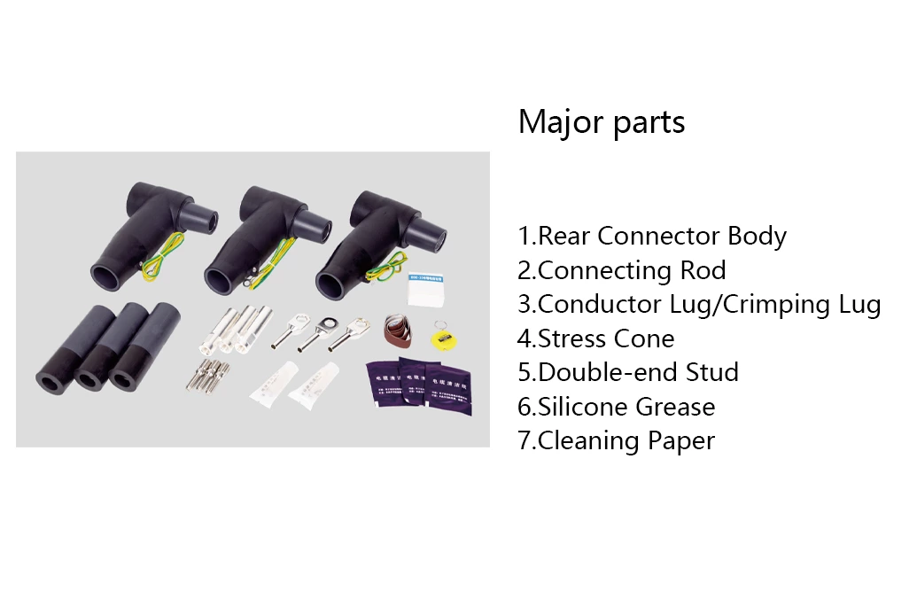
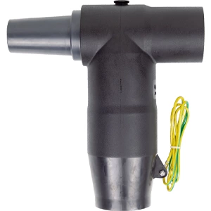
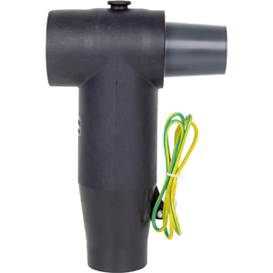
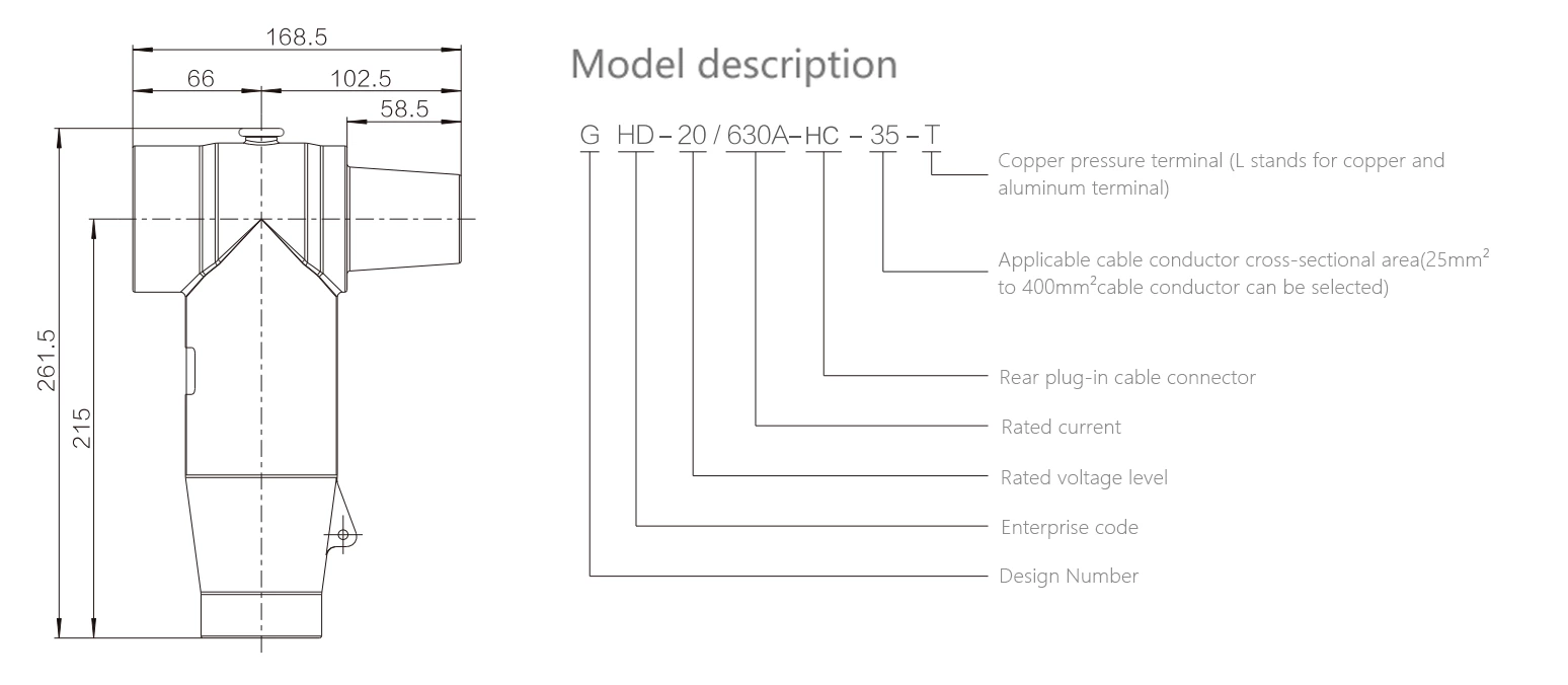
The 630 A rear plug-in cable connector is used in conjunction with the front plug-in cable connector product. It provides branching for 630 A circuits but cannot be directly connected to products such as bushings. Its rear end can be sealed with an insulator or extended to connect another rear plug-in cable connector and rear plug-in arrester.
Utilizing advanced rear injection technology, the outer layer features a semi-conductive shielding layer that is touch-safe, ensuring personal safety. The unique stress cone structure effectively dissipates electric field stress, resolving electric field stress issues at the cut-off point of the cable shielding layer. It offers expandability, flexible installation and removal, and enables T-type cable connections. The product is fully sealed, fully insulated, fully protected, maintenance-free, submersible-resistant, and pollution-resistant.
Technical Data
| Rated voltage | 18/20 kV | ||
| Rated current | 630 A | ||
| AC Withstand Voltage for 5min | 81 kV | ||
| Partial Discharge | 30 kV,Q≤10 pC | ||
| Impulse Withstand Voltage(10 times foreach polarity) | 170 kV | ||
| Screen Resistance | ≤5000 Ω | ||
| Reference standards:GB/T 12706.4、IEC 60502-4 | |||
Models Selection
| Product model | Cross sectional area nominal(mm²) | 18/20 kV voltage level cable insulation outer diamerer(mm²) | |||
| GHD-24/630A-HC-35 | 35 | 24 | |||
| GHD-24/630A-HC-50 | 50 | 25.9 | |||
| GHD-24/630A-HC-70 | 70 | 27.4 | |||
| GHD-24/630A-HC-95 | 95 | 29.1 | |||
| GHD-24/630A-HC-120 | 120 | 30.5 | |||
| GHD-24/630A-HC-150 | 150 | 32.1 | |||
| GHD-24/630A-HC-185 | 185 | 33.6 | |||
| GHD-24/630A+C-240 | 240 | 35.9 | |||
| GHD-24/630A-HC-300 | 300 | 38.1 | |||
| GHD-24/630A-HC-400 | 400 | 41.6 | |||
Product accessory Illustration