High-Speed Rail Traction Transformer Separable Connectors: Domestic Breakthrough in Power Transfer Quality Under Extreme Conditions
- Rated voltage:
- 35 kV
- Rated current:
- 630 A
- AC Withstand Voltage for 5min:
- 117 kV
- Partial Discharge:
- 45 kV,≤10 pC
- Impulse Withstand Voltage(10 times foreach polarity):
- 200 kV
- Screen Resistance:
- ≤5000 Ω
- Reference standards:
- GB/T 12706.4、IEC 60502-4
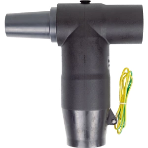
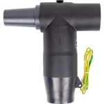
Domestic 25 kV, 630 A separable connector now passes 140°C oil, ≤5 pC partial discharge, and GB/T 21563 Class 1B vibration. Three changes deliver this: 140°C Tg epoxy bushing, semi-circular boss seals, and an integrated screened T-body. Verification covers AC 136 kV/5 min, cantilever 300 N/1 min, and EN 45545 HL2 fire rating.
Why 140°C Oil and Vibration Break Imported Units
Traction transformer oil reaches 140°C. Imported Separable Connectors often use epoxy with Tg near 125°C. The bushing softens, seals open, and oil leaks. Vibration from 5 Hz to 150 Hz adds fatigue. Moisture enters, and partial discharge rises. Four failure modes follow: epoxy deformation, seal micro-channels, moisture ingress, and stress-cone discharge.
Domestic Breakthrough: Three Engineering Levers
Epoxy Tg Raised from 125°C to 140°C
Curing agents and additives raise bushing Tg to 140°C. The body stays rigid from -40°C to 140°C. Oil leakage from thermal softening stops.
Semi-Circular Boss Sealing
Semi-circular bosses on the T-body and cap create multiple compression zones. Contact pressure holds under random vibration. Moisture and waterproofing type tests pass at a national laboratory.
Integrated Screened T-Body
The stress cone and T-body are molded as one part. Fewer mating interfaces lower partial discharge risk. The outer semi-conductive shield remains submersible.
How to Verify Power Transfer Quality at the Separation Interface
Electrical Tests
-
AC withstand: 136 kV, 5 min
-
Partial discharge: ≤5 pC at 53 kV
-
Impulse: 250 kV, ±10 shots
Mechanical Tests
-
Cantilever: 300 N, 1 min
-
Vibration: GB/T 21563 Class 1B, 5–150 Hz
Environmental Tests
-
Moisture and waterproofing
-
Thermal cycling
-
Fire: EN 45545 HL2
Screened separable connectors pass all six checks.
Import vs Domestic: Test Records and Standards
| Parameter | Imported | Domestic |
|---|---|---|
| AC withstand, T-body | 124 kV/5 min | 136 kV/5 min |
| Partial discharge | ≤10 pC | ≤5 pC |
| Tg, bushing | ~125°C | 140°C |
| Cantilever load | 250 N | 300 N/1 min |
| Fire rating | Variable | EN 45545 HL2 |
Test report No. 2023-XXX from a national insulation laboratory. Standards: GB/T 28427, GB/T 21563, EN 45545.
Selection and Installation Steps for Rail Projects
Selection:
-
Confirm 25 kV catenary → 26/35 kV rating
-
Verify 630 A current
-
Demand Tg ≥140°C
-
Require PD ≤5 pC at 1.73 U0
-
Check GB/T 21563 Class 1B
-
Confirm EN 45545 HL2
Installation:
-
Clean interface
-
Apply specified torque
-
Seat stress cone
-
Connect shield
-
Re-test PD
Separable insulated connectors for 25 kV systems follow these steps.
Field Troubleshooting
-
Oil leak: check Tg and seal compression
-
PD rise: inspect stress cone and moisture
-
Temperature rise: verify torque and contact resistance
A separable cable connector with correct interface pressure avoids these faults.
FAQ
Q: What oil temperature can the interface handle?
A: 140°C continuously, 30-year design life.
Q: How is vibration sealed?
A: Semi-circular bosses keep compression under 5–150 Hz.
Q: Which type suits branching?
A: Rear plug-in units extend to another rear unit.
Q: What partial discharge limit applies?
A: ≤5 pC at 53 kV for the T-body.
Product features
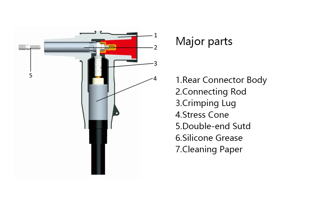
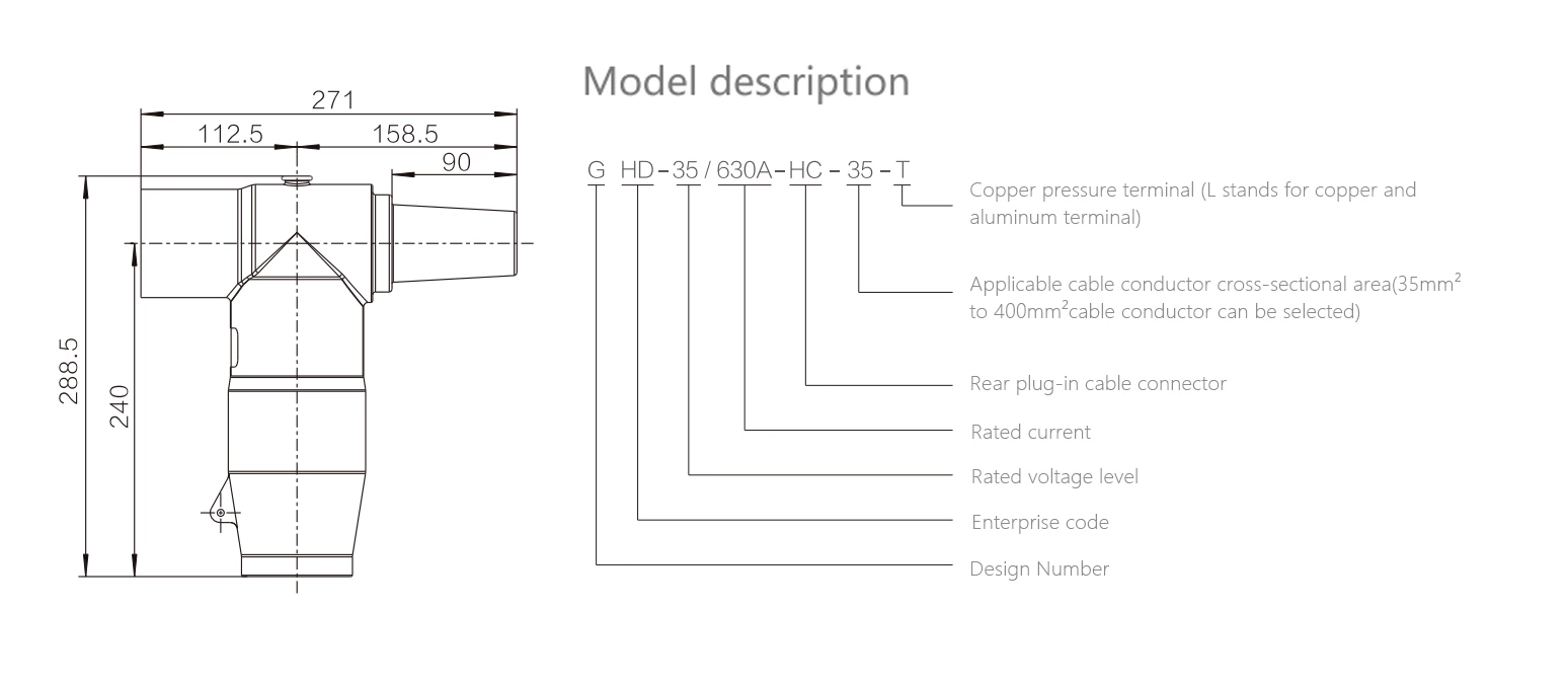
The 630 A rear plug-in cable connector is used in conjunction with the front plug-in cable connector product. It provides branching for 630 A circuits but cannot be directly connected to products such as bushings. Its rear end can be sealed with an insulator or extended to connect another rear plug-in cable connector and rear plug-in arrester.
Utilizing advanced rear injection technology, the outer layer features a semi-conductive shielding layer that is touch-safe, ensuring personal safety. The unique stress cone structure effectively dissipates electric field stress, resolving electric field stress issues at the cut-off point of the cable shielding layer. It offers expandability, flexible installation and removal, and enables T-type cable connections. The product is fully sealed, fully insulated, fully protected, maintenance-free, submersible-resistant, and pollution-resistant.
Technical Data
| Rated voltage | 35 kV | ||
| Rated current | 630 A | ||
| AC Withstand Voltage for 5min | 117 kV | ||
| Partial Discharge | 45 kV,≤10 pC | ||
| Impulse Withstand Voltage(10 times foreach polarity) | 200 kV | ||
| Screen Resistance | ≤5000 Ω | ||
| Reference standards:GB/T 12706.4、IEC 60502-4 | |||
Models Selection
| Product model | Cross sectional area nominal(mm²) | 26/35 kV voltage level cable insulation outer diamerer(mm²) | ||
| GHD-35/630A-HC-35 | 35 | 29 | ||
| GHD-35/630A-HC-50 | 50 | 31 | ||
| GHD-35/630A-HC-70 | 70 | 32.6 | ||
| GHD-35/630A-HC-95 | 95 | 34.2 | ||
| GHD-35/630A-HC-120 | 120 | 35.6 | ||
| GHD-35/630A-HC-150 | 150 | 37.2 | ||
| GHD-35/630A-HC-185 | 185 | 38.7 | ||
| GHD-35/630A-HC-240 | 240 | 41.1 | ||
| GHD-35/630A-HC-300 | 300 | 43.2 | ||
| GHD-35/630A-HC-400 | 400 | 46.6 | ||
| GHD-35/630A-HC-500 | 500 | 49.2 | ||
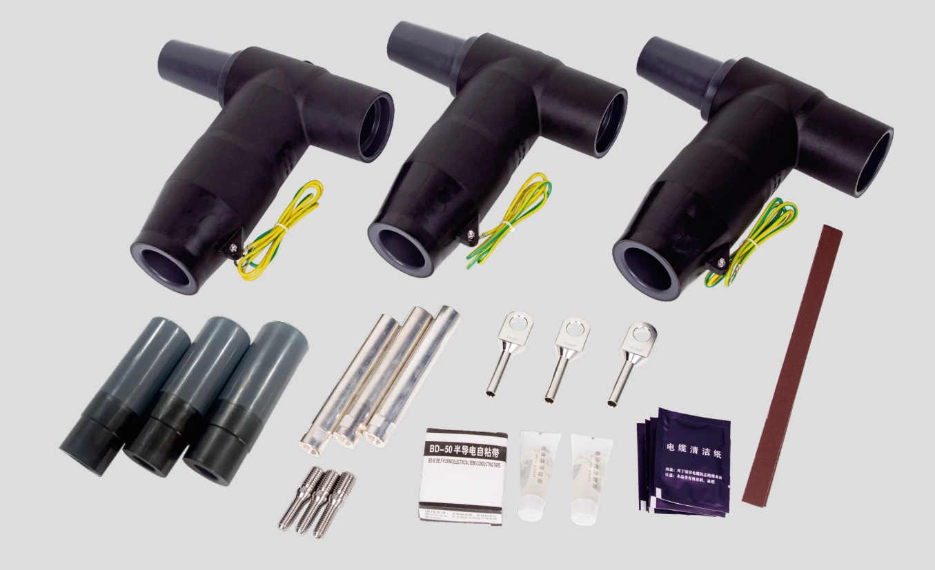
Product accessory Illustration