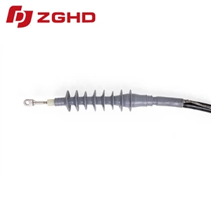
Cold Shrink Cable Accessories Cool Shrink Joint Termination
- Power Frequency Withstand Voltage:
- 117 kV, 5 min, No Breakdown
- Partial Discharge Test:
- Partial Discharge Magnitude≤ 10 pC at 45 kV
- Impulse Voltage Test:
- 200 kV, 10 positive and 10 negative impulses, no breakdown
- Constant Voltage Load Cycling Test (in Air):
- 65 kV, conductor temperature 95–100 ℃, total 60 cycles, no breakdown, no flashover
- Moisture Test (Indoor):
- 32.5 kV, 300 h, no breakdown, no flashover
- Salt Spray Test (Outdoor):
- 32.5 kV, 1000 h, no breakdown, no flashover
- DC Withstand Voltage:
- 104 kV, 15 min, No Breakdown
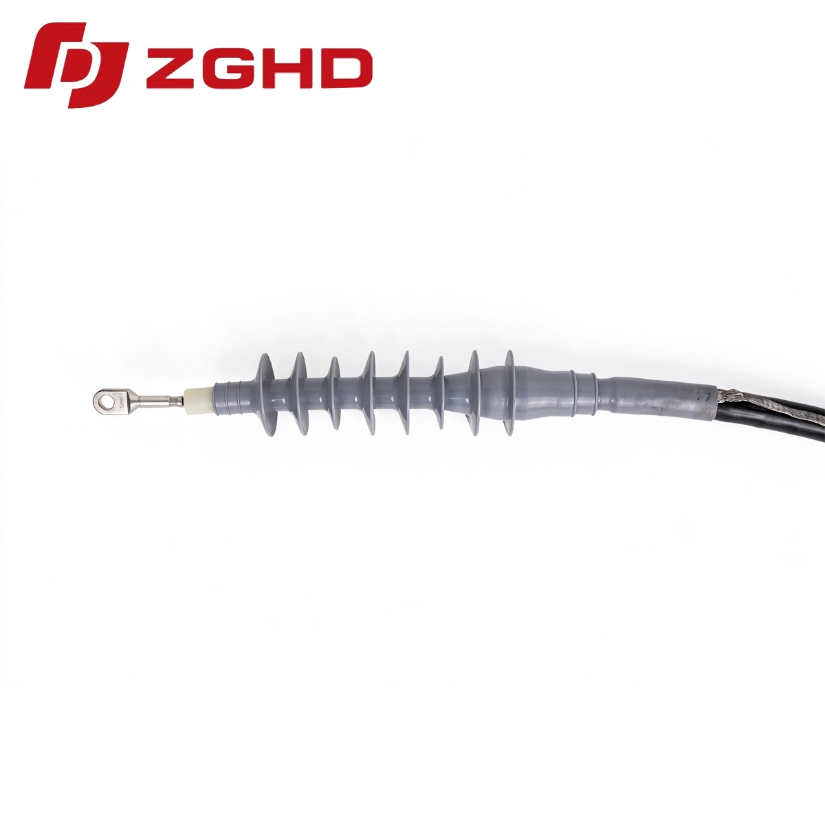
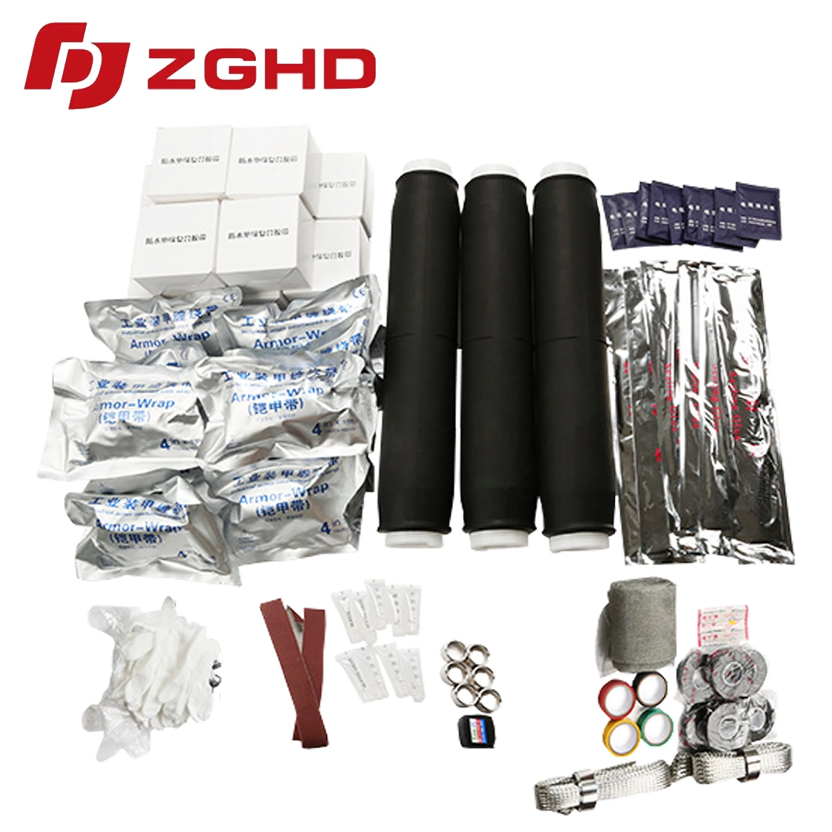
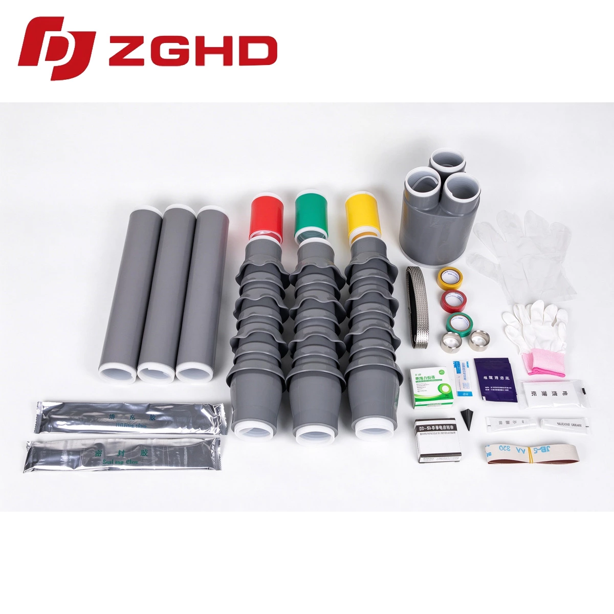
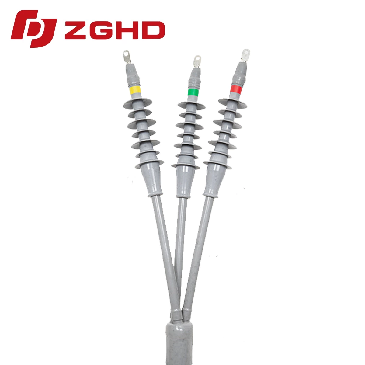
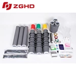
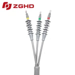
Medium-voltage power distribution networks require constant radial pressure and moisture sealing at connection interfaces. Cold Shrink Cable Accessories utilize pre-expanded elastomeric silicone rubber sleeves to eliminate open flames on site. When splicing medium-voltage feeder lines, cold shrinkable cable joints deliver uniform interface recovery across cross-linked polyethylene insulation.
Structural Advantages and Operational Reliability
Rapid Installation Sequence
-
Strip cable outer jackets and prepare insulation shields to exact dimensions.
-
Position the cool shrink assembly over the prepared conductor core.
-
Extract the internal plastic spiral support counterclockwise without torches or heat guns.
Core technical characteristics include:
-
Active radial pressure accommodates continuous thermal expansion cycles.
-
High-grade silicone provides hydrophobic tracking resistance in contaminated atmospheres.
-
Integrated geometric stress cones minimize partial discharge below 10 pC at rated voltages.
Technical Specifications
| Parameter | Rated Value | Standard Compliance |
|---|---|---|
| Voltage Range | 26/35 kV | IEC 60502-4 |
| Dielectric Strength | ≥ 25 kV/mm | GB/T 12706.4 |
| Partial Discharge Level | ≤ 10 pC at 2 U0 | IEEE 404 |
| Radial Pressure Retention | > 0.15 MPa | CENELEC HD 629.1 |
Substation and Feeder Network Deployment
Overhead and Switchgear Connections
Deploying an indoor or outdoor cold shrinkable termination ensures dielectric protection along exposed bushings and overhead line risers. Molded rain sheds resist ultraviolet radiation, surface contamination, and leakage currents during heavy precipitation.
Underground Vault Splices
Direct-buried conduits and manholes often encounter water ingress and ground movement. In these environments, each cold shrinkable joint maintains an IP68 seal via hydrophobic mastic strips and continuous mechanical memory, preventing moisture intrusion during severe electrical load shifts.
26/35 kV Fully Cold Shrink Three-Core Terminal – Installation Outline Drawing

Electrical Performance Tests
| No. | Test Item | Standard Requirements |
| 1 | Power Frequency Withstand Voltage | 117 kV, 5 min, No Breakdown |
| 2 | DC Withstand Voltage | 104 kV, 15 min, No Breakdown |
| 3 | Partial Discharge Test | Partial Discharge Magnitude≤ 10 pC at 45 kV |
| 4 | Impulse Voltage Test | 200 kV, 10 positive and 10 negative impulses, no breakdown |
| 5 | Constant Voltage Load Cycling Test (in Air) | 65 kV, conductor temperature 95–100 ℃, total 60 cycles, no breakdown, no flashover |
| 6 | Moisture Test (Indoor) | 32.5 kV, 300 h, no breakdown, no flashover |
| 7 | Salt Spray Test (Outdoor) | 32.5 kV, 1000 h, no breakdown, no flashover |
Product overview
◆The product is available in single-core, two-core, three-core, four-core, and five-core versions, and has been widely used for low-voltage cable terminations and intermediate connections.
◆Excellent surface hydrophobicity, ensuring the product maintains strong resistance to contamination.
◆Compact size, lightweight, and reliable performance.
◆Application Scope: The product demonstrates excellent cold and heat resistance, making it particularly suitable for high-altitude, cold, humid, salt-spray, and heavily polluted environments.
Installation requires no open flame, making it ideal for flammable and explosive areas such as petroleum, chemical, mining, and tunneling sites.
 |
 |
 |
 |
| 26/35 kV Single-Core Cold Shrink Outdoor Termination – Installation Drawing | 26/35 kV Three-Core Cold Shrink Outdoor Termination – Installation Drawing | 26/35 kV Three-Core Cold Shrink Outdoor Termination – Supporting Drawing | 26/35 kV Three-Core Cold Shrink Intermediate Connection – Supporting Drawing |
Technical Data - Model Selection
| Product Type | Model | Conductor Cross-section(mm²) |
| 26/35 kV Cold Shrink Indoor Termination | GHD-35HNLS-3(1)*50-630 | 50-630 |
| 26/35 kV Cold Shrink Outdoor Termination | GHD-35HWLS-3(1)*50-630 | 50-630 |
| 26/35 kV Cold shrink Joint | GHD-35JTLS-3(1)*50-630 | 50-630 |