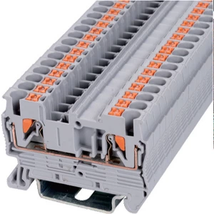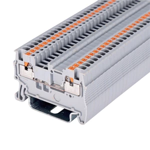
No Screws, No Loosening? How Push-in Type Terminal Blocks Work
- Type:
- Feed-through terminal block
- Nominal Voltage:
- 800 V
- Nominal Current:
- 32 A
- Number Of Connections:
- 2
- Number Of Positions:
- 1
- Connection Method:
- Push-in connection
- Rated Cross Section:
- 4 mm²
- Mounting type:
- DIN Rail (EN 60715)
- Compatible Rail:
- NS 35/7,5, NS 35/15
- Cross Section:
- 0.2 mm² - 6 mm²
- Color:
- gray
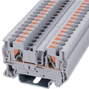
Push-In Type Terminal Blocks hold wires with a stainless steel spring, not screw torque. The spring applies constant pressure, so vibration and thermal cycling do not loosen the contact. Installation follows four steps: strip the conductor, insert it, let the spring lock, and tug-test. No retightening is needed. This is the core answer.
Why Spring Clamp Technology Works
🔹 Chromium-nickel leg spring opens on insertion.
🔹 Spring presses the wire against the current bar.
🔹 Elastic energy keeps the contact interface gas-tight.
🔹 Yield strength limit keeps each insertion reversible.
🔹 Repeated use does not reduce clamping force.
Screw vs. Spring-Clamp Connections
| Parameter | Screw Terminal | Spring-Clamp Terminal |
|---|---|---|
| Contact pressure | Manual torque | Constant spring force |
| Repeated insertions | ≤10 cycles | ≥50 cycles |
| Vibration behavior | Can loosen | Self-adjusting |
| Maintenance | Re-torque | None |
| Wiring time per conductor | 6–8 s | Under 2 s |
A screw terminal depends on correct torque at every point. Vibration and temperature swings reduce pressure over time. A push fit connector block removes that variable. The spring compensates for wire settling and thermal expansion.
Selection Guide
Wire Size, Current, and Voltage
A 4 mm² feed-through terminal carries 800 V and 32 A. It accepts rigid conductors from 0.2 to 6 mm² and flexible conductors from 0.2 to 4 mm². Strip length is 8–10 mm.
Materials and Certifications
Housing: PA66, UL94 V-0. Spring: stainless steel. Certifications: IEC 60947-7-1, UL, CE, RoHS. A push in din rail terminal blocks system mounts on 35 mm rails.
Installation and Verification
-
Strip 8–10 mm of insulation.
-
Insert a rigid or ferruled wire.
-
Push until the spring locks.
-
Tug the wire to confirm retention.
Common errors:
-
Stripping too long or too short.
-
Using stranded wire without a ferrule.
-
Not inserting fully.
-
Mixing wire types in one clamp.
Standards and Testing
IEC 60947-7-1 defines mechanical and thermal requirements for screwless clamping units. Spring-clamp designs are recognized as maintenance-free under this standard. Pull-out tests verify retention without slippage or strand damage.
Test results for a push in wire terminal block include:
⚡ Contact resistance below 1 mΩ.
⚡ Pull-out force above 50 N.
⚡ Salt-mist resistance up to 1,000 hours.
⚡ 30-day temperature rise trials.
⚡ 14-day heat cycling evaluations.
Applications and Limits
Push-in terminals suit motor control panels, photovoltaic systems, energy storage, and rail transport. A push fit terminal resists continuous vibration.
Do not use push-in connections for:
-
Fine stranded wire without a ferrule.
-
Ultra-high-frequency insertion cycles.
-
Highly corrosive environments without evaluation.
Troubleshooting
| Problem | Cause | Action |
|---|---|---|
| Wire will not insert | Wrong strip length | Re-strip to 8–10 mm |
| Wire pulls out | Not fully seated | Insert until spring locks |
| Overheating | Loose contact | Replace terminal and rewire |
| Strands spread | No ferrule | Add ferrule and reinsert |
FAQ
Q: Are push-in connections maintenance-free?
A: Yes. The spring maintains continuous force without operator action.
Q: Can stranded wire be used?
A: Yes, with a ferrule. The ferrule keeps strands together.
Q: What wire sizes fit?
A: Common systems accept 0.14 to 16 mm².
Q: Is a tool required?
A: No tool is needed for insertion. A screwdriver may release the spring.
Q: Do push-in terminals resist vibration?
A: Yes. The spring self-adjusts as conductors expand and contract.
| Wiring Diagram |  |
||
| Thickness / Width / Height (mm) | 6.2×56×35.5 | ||
| Technical Parameters | |||
| Rated Data | Voltage (V) | 800 | |
| Current (A) | 32 | ||
| Cross-section (mm²) | 4 | ||
| Crimping Range | Rigid Wire (mm²) | 0.2-6 | |
| Flexible Wire (mm²) | 0.2-4 | ||
| Insulating Material | PA | ||
| Flame retardant rating UL-94 | V0 | ||
| Stripping Length (mm) | 10 | ||
| Install the Guide Rails | TH35-7.5/TH35-15 | ||
| model | |||
| Partition plate | 4G | 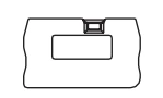 |
|
| Plug-in Bridge | 2P | FBS 2-6 | 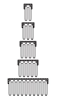 |
| 3P | FBS 3-6 | ||
| 4P | FBS 4-6 | ||
| 5P | FBS 5-6 | ||
| 10P | FBS 10-6 | ||
| Marker Strip | blank | ZB6 | 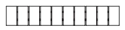 |
| Horizontal Printing | ZB6 | 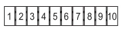 |
|
| Vertical Printing | ZB6 |  |
|
| Dimensions | 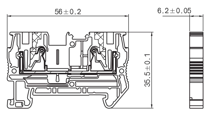 |
||