Why 95% Iacs Copper Still Overheats In Push-in Terminal Blocks
- Type:
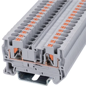
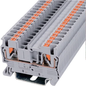
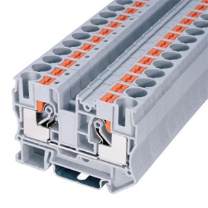
- Feed-through terminal block
- Nominal Voltage:
- 1000 V
- Nominal Current:
- 57 A
- Number Of Connections:
- 2
- Rated Cross Section:
- 10 mm²
- Mounting type:
- DIN Rail (EN 60715)
- Compatible Rail:
- NS 35/7,5, NS 35/15
- Cross Section:
- 0.5 mm² - 16 mm²
- Color:
- gray
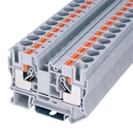
A copper alloy rated at 95% IACS can still overheat inside a push-in type terminal block. The %IACS rating describes bulk material conductivity, not interfacial contact resistance. Insertion friction generates micro-oxidation layers and wear debris on the conductor surface. Even premium alloys develop rising resistance under real operating conditions. Engineers should measure millivolt drop first, then inspect plating, surface roughness, and spring pressure.
What %IACS Measures and What It Ignores
The %IACS rating reflects bulk conductivity tested under ideal laboratory conditions. It excludes the contact interface, where four resistance layers form: film resistance, constriction resistance, contamination layers, and spring force decay.
Tinned copper holds 95% to 99% IACS while resisting oxidation. The tin layer can be scraped away during repeated insertions, exposing base metal to air and forming insulating oxide films inside the housing.
Degradation Mechanism Inside Push-In Type Terminal Blocks
Stage 1 — Plating Abrasion During Insertion
Each insertion scrapes micro-portions of tin or silver plating from the contact surface. Dynamic friction strips plating during repeated actuation, exposing base metal to ambient air.
Stage 2 — Micro-Oxidation and Wear Debris
Exposed copper alloy oxidizes quickly. Under vibration, oxide content at the interface can rise sharply. These oxides act as high-resistivity layers blocking current transmission.
Stage 3 — Thermal-Mechanical Coupling
-
Interfacial resistance converts current into concentrated heat
-
Heat accelerates spring stress relaxation
-
Reduced pressure raises resistance further
-
The cycle compounds until micro-arcing begins
| Cycle Count | Contact Resistance | Spring Force Retention |
|---|---|---|
| Initial | Baseline | 100% |
| 50 cycles | Slight rise | 95% |
| 200 cycles | Moderate rise | 82% |
| 500 cycles | Sharp rise | 65% |
Three System Variables That Matter More Than IACS
Coating Wear Resistance
Tin, silver, and nickel platings differ in hardness and wear life. Thicker reflow-treated coatings survive more insertion cycles before exposing base metal.
Surface Roughness Control
Surfaces held near Ra0.8 form stable multi-point contact with conductor cores. Push fit din rail terminals with controlled roughness hold resistance below 5 milliohms after aging tests.
Spring Pressure Matching
A push in type terminal block depends on stainless steel springs to sustain gas-tight contact. Insufficient pressure inside a push fit terminal block lets microscopic wire movements pull air into gaps, forming oxide layers.
Selection and Verification Checklist
-
Plating thickness above 0.1 μm with reflow treatment
-
High-yield stainless steel springs rated for salt-mist exposure
-
Insertion force below 15 N to prevent over-extension
-
Aged contact resistance tested per IEC 60947-7-1
-
Pull-out force above 50 N after temperature cycling
Field checks include millivolt drop testing and thermal imaging after warm-up. Both detect anomalies before joints fail visibly.
Frequently Asked Questions
Q: Does higher IACS copper prevent terminal heating?
A: No. Bulk conductivity does not control interfacial resistance. Plating wear and spring force dominate long-term performance.
Q: Do push fit terminal blocks need silver plating?
A: Silver suits high-cycle and high-temperature applications. Tin works for moderate cycles if thickness and reflow quality are controlled.
Q: How often should contact resistance be measured?
A: Measure after installation and at scheduled maintenance intervals. Thermal imaging identifies rising resistance between scheduled checks.
| Wiring Diagram |  |
||
| Thickness / Width / Height (mm) | 10.2×68×50 | ||
| Technical Parameters | |||
| Rated Data | Voltage (V) | 1000 | |
| Current (A) | 57 | ||
| Cross-section (mm²) | 10 | ||
| Crimping Range | Rigid Wire (mm²) | 1.5-16 | |
| Flexible Wire (mm²) | 1.5-16 | ||
| Insulating Material | PA | ||
| Flame retardant rating UL-94 | V0 | ||
| Stripping Length (mm) | 18 | ||
| Install the Guide Rails | TH35-7.5/TH35-15 | ||
| model | |||
| Partition plate | 10G | 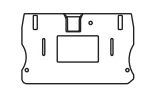 |
|
| Plug-in Bridge | 2P | FBS 2-10 |  |
| Marker Strip | blank | ZB10 |  |
| Horizontal Printing | ZB10 |  |
|
| Vertical Printing | ZB10 | 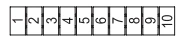 |
|
| Dimensions | 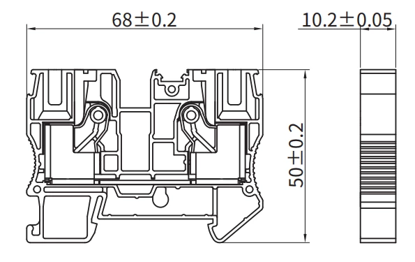 |
||