How Should Fuse Terminals Be Wired To Protect Downstream Equipment?
- Type:
- Fuse modular terminal block
- Fuse Type:
- Glass / ceramics / ... G / 5 x 20 / 5 x 25
- Nominal Voltage:
- 800 V
- Nominal Current:
- 6.3 A
- Number Of Positions:
- 1
- Connection Method:
- Screw connection
- Rated Cross Section:
- 4 mm²
- Cross Section:
- 0.2 mm² - 4 mm²
- Color:
- black
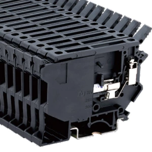
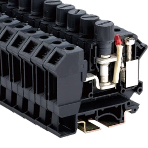
Wiring a fuse terminal block correctly requires landing the upstream supply conductor on the feed side, routing the downstream load conductor from the protected side, and seating the block securely on a DIN rail before inserting the fuse. A fuse block terminal protects downstream equipment only when current passes through the fuse element between the two connection points, not around it.
Upstream and Downstream Connections
The feed side accepts the incoming supply conductor from the distribution bus or upstream protective device. This terminal point sits on one side of the internal fuse carrier. The load side connects the outgoing conductor that feeds downstream equipment. Current must flow through the replaceable fuse link between these two points. Reversing the conductors bypasses the fuse entirely and leaves downstream devices exposed to overcurrent.
Step-by-Step Wire Termination
-
De-energize the circuit and verify absence of voltage at the terminal point.
-
Strip the conductor insulation to the length specified for the connection method.
-
Loosen the clamping screw on the entry slot and insert the exposed conductor fully.
-
Tighten the screw to the rated torque. For a screw terminal fuse block with an M3 screw, the tightening torque is 0.6 Nm.
-
Confirm the conductor is secure by applying gentle pull tension.
DIN Rail Mounting
Universal mounting feet on fused terminal blocks snap onto standard top-hat (Ω profile) and G-profile DIN rails. The block must sit flush against the rail without wobble. Adjacent blocks align through their side profiles to form a continuous strip. A loose block on the rail increases contact resistance at the screw connection and can cause localized heating under load.
Identification and Marking
Terminal blocks require provision for identification marks or numbers linking each terminal to its circuit. Marking tags slide into the designated slot on the block face. Label both the upstream feed and the downstream load side clearly. This practice allows maintenance personnel to trace circuits without guesswork during fault finding or equipment changes.
Spare Fuse Handling
Some fused terminal blocks include a built-in spare fuse holder within the fuse carrier. This holder keeps a replacement fuse on hand, reducing downtime when a fuse opens during service. The fuse carrier accepts 5 × 20 mm and 5 × 25 mm cartridge fuses, with current ratings from 0.5 A to 20 A depending on the fuse selected.
Key Ratings at a Glance
| Parameter | Specification |
|---|---|
| Rated voltage | 800 V |
| Rated current | 6.3 A |
| Rated cross-section | 4 mm² |
| Connection method | Screw |
| Wire range | 0.2 – 4 mm² |
| Screw torque | M3 / 0.6 Nm |
| Housing material | PA, UL-94 V0 |
These values reflect a representative fuse terminal specification and should be verified against the specific block in use.
Common Wiring Faults to Avoid
-
Landing both conductors on the same side of the fuse carrier, which bypasses protection.
-
Under-tightening the screw, which creates a high-resistance joint that overheats under load.
-
Installing a fuse with a higher current rating than the downstream conductor can carry.
Each of these faults defeats the purpose of the fused terminal block and places downstream equipment at risk.
| Model | Function | Wire IEC cross-section | Wire UL | Thickness |
| JHD5-4RD | 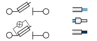 |
4 mm² 2.5 mm² 4 mm² |
12 AWG 14 AWG 12 AWG |
8.2 mm |
| Maximum current | Number of packages | Thickness/Height( )/Width mm )/Width mm |
Rated voltage/rated current/rated cross-sectior |
| 6.3 A | 45 | 8.2/56.5/72.5 | 800 V/6.3 A/4 mm² |
Specfication:
| With Light | With Light
|
||||||||||||
Fuse
|
|||||||||||||
| Marking tags | ZB8 | ||||||||||||
| Screw/Tightening torque(Nm) | M3/0.6 | ||||||||||||
| Material | PA | ||||||||||||
| Flame retardant rating UL-94 | V0 | ||||||||||||
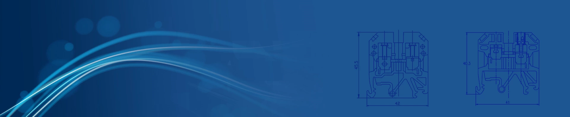
| Dimensions | 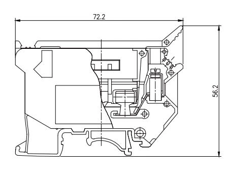 |
With universal mounting feet for standard top-hat(Ω profile) and G-profile DIN rail mounting.