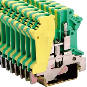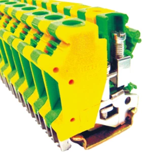
The Wiring Of The Pe Terminal Differs Significantly In Tn, Tt, And It Systems
- Type:
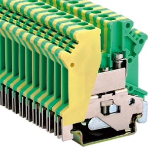
- Protective conductor terminal block, When aligning with a feed-through terminal block with the same shape, an end cover must be interposed with insulation voltages of > 690 V
- Number Of Connections:
- 2
- Number Of Positions:
- 1
- Connection Method:
- Screw connection
- Cross Section:
- 0.2 mm² - 4 mm²
- Mounting Method:
- PE foot with mounting screw, M2.5
- Color:
- green-yellow
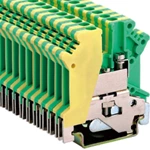
Grounding terminal blocks are selected by earthing system, not wire size alone. TN-S needs a low-impedance PE collection point. TT needs a verified bond to a local electrode. IT needs equipotential bonding without an unintended earth path. Match the terminal to the fault-current path: TN-S returns through PE, TT returns through earth, IT relies on insulation monitoring. Check conductor size, fault rating, DIN rail continuity, and labelling before energising.
Quick Selection Checklist
-
Identify the earthing system.
-
Confirm PE cross-section.
-
Check short-time withstand current.
-
Verify DIN rail bonding method.
-
Test continuity before power.
| Item | TN-S | TT | IT |
|---|---|---|---|
| PE return path | Metallic | Earth | High impedance |
| Main protection | Overcurrent | RCD | IMD |
| Terminal role | PE collection | Electrode bond | Equipotential |
PE Conductor Roles by System
TN-S System
PE and N stay separate downstream of the source. Fault current returns through PE, producing high short-circuit current. The terminal must carry that current until the protective device trips.
TT System
PE connects to an independent earth electrode. Fault current returns through soil. An RCD clears the fault. The earth terminal connector must bond reliably to that electrode.
IT System
The first fault does not disconnect. An insulation monitoring device alarms. The terminal ground block maintains equipotential bonding without adding an unintended low-impedance earth path.
Selecting Terminals for Each System
TN-S
Use a ground terminal block din rail to gather PE conductors. Keep impedance low. PE and N never share a terminal downstream.
TT
A grounding din rail works only when bonded to the local electrode. Continuity testing is mandatory. RCD protection handles disconnection.
IT
Use the terminal for equipotential reference. Confirm no unintended earth path exists. Measure insulation resistance between the PE busbar and earth.
Conductor Cross-Section
PE matches phase conductors up to 16 mm² per IEC 60947-7-2. Spring-clamp terminals accept 0.5–6 mm² copper at up to 800 V. Screw terminals for M4 ring lugs need 1.2–2 N·m torque.
Product Example
The JHD5-2.5JD protective conductor terminal block handles 0.5–2.5 mm² at 24 A, 660 V, with 20 mm width. It suits control-circuit PE paths.
Installation and Verification
Pre-Installation Checks
-
Confirm system type.
-
Check terminal rating.
-
Inspect rail continuity.
Installation Steps
-
Mount terminal on rail.
-
Connect PE conductor.
-
Tighten to specified torque.
-
Label green/yellow.
-
Test bonding resistance.
-
Record the result.
Testing Methods
Measure continuity from the terminal to the main earthing bar. For TT, verify the electrode bond. For IT, check insulation resistance.
Common Errors
-
Sharing PE with signal ground.
-
Assuming the rail is earthed.
-
Skipping torque checks.
-
Mixing PE and N in TN-S downstream.
FAQ
Q: What is a grounding terminal block?
A: A terminal that collects and bonds protective conductors.
Q: Can PE and N share a terminal?
A: Only at the source earthing point in TN systems, not downstream.
Q: Does DIN rail need separate earth?
A: Yes, when the terminal bonds through the rail.
Q: How is PE bonding tested?
A: Measure resistance from the terminal to the main earthing bar.
Q: What torque for PE screws?
A: Follow manufacturer guidance. M4 lugs often use 1.2–2 N·m.
| Model | Function | Wire IEC cross-section | Wire UL |
| JHD5-2.5JD | 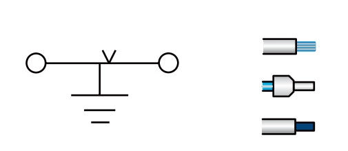 |
2.5 mm² 1.5 mm² 2.5 mm² |
14 AWG 16 AWG 14 AWG |
| Thickness | Number of packages | Thickness/Height( )/Width mm )/Width mm |
Rated voltage/rated current/rated cross-sectior |
| 5.2 mm | 120 | 5.2/47/42.5 | -/34 A/2.5 mm² |
Specfication:
| Marking tags | ZB5 |
| Screw/Tightening torque(Nm) | M3/0.6 |
| Material | PA |
| Flame retardant rating UL-94 | V0 |
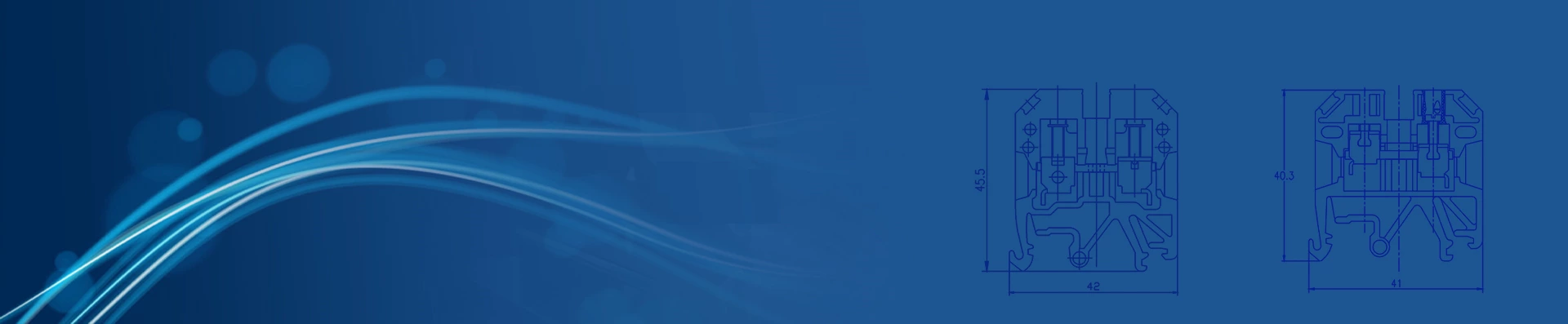
| Dimensions | 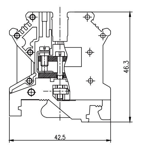 |
With universal mounting feet for standard top-hat(Ω profile) and G-profile DIN rail mounting.