How Plating Thickness Affects Insertion Force In Push-in Type Terminal Blocks?
- Type:
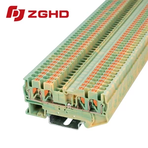
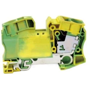
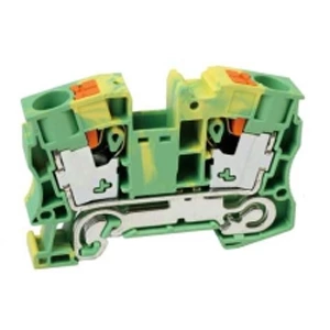
- Protective conductor terminal block
- Number Of Connections:
- 2
- Connection Method:
- Push-in connection
- Rated Cross Section:
- 16 mm²
- Mounting type:
- DIN Rail (EN 60715)
- Compatible Rail:
- NS 35/7,5, NS 35/15
- Cross Section:
- 0.5 mm² - 25 mm²
- Color:
- green-yellow
Tin thickness on the sliding contact controls insertion force in push-in type terminal blocks. Target 0.1–0.3 μm on the side with greater sliding distance. This cuts insertion force by over 30% compared with a 1.0 μm coating while contact resistance stays below 1.0 mΩ. Add a 1–1.3 μm nickel underlayer to block copper diffusion.
The Mechanical Role of Plating
Plating is specified for corrosion protection and conductivity. Its mechanical function is often overlooked. Tin is a soft interface between two harder metals. A thick layer deforms and cold-welds during insertion, adding friction. A thin layer lets the copper alloy hardness—often above 150 HV—govern the surface. This suppresses adhesion and lowers engagement force.
Friction, Adhesion, and Cold Welding
Insertion force depends on normal force, friction coefficient, and real contact area. A thick tin layer smears during mating, increasing contact area and friction. Repeated insertions cause tin transfer and erratic force readings. With a thin coating, the substrate hardness dominates. The push fit terminal then slides with less resistance and more consistent behavior across mating cycles.
Test Data Across Tin Thickness Ranges
| Sliding Side Tin | Insertion Force | Contact Resistance | Corrosion Coverage |
|---|---|---|---|
| 1.0 μm | Baseline | Lowest | Full |
| 0.3–0.6 μm | Moderate drop | Low | Full |
| 0.1–0.3 μm | >30% drop | <1.0 mΩ | Adequate |
| <0.1 μm | Further drop | Local rise risk | Incomplete |
Test conditions: 30-pole connector, fixed spring force, IEC 60512-13-2, 50 mating cycles.
A push in wire terminal block with 0.1 μm tin on the male side and 0.3–1.0 μm on the female side shows the largest force reduction without exceeding resistance limits.
Tin, Gold, Silver, and Nickel Underlayers
Gold and silver platings offer lower resistance but cost more. Tin remains common for push in din rail terminal blocks in control cabinets. A nickel underlayer at 1–1.3 μm prevents copper diffusion into tin. Without it, hard Cu₆Sn₅ intermetallics form and raise insertion force over time. Reflow treatment followed by controlled annealing stabilizes the surface.
How to Measure Insertion Force Correctly
-
Use a push-pull tester with constant speed.
-
Record force over full insertion distance.
-
Measure contact resistance after each cycle.
-
Test at 23°C and 50% relative humidity.
-
Run at least 50 mating cycles per sample.
A push fit connector block tested this way produces a force curve with a clear peak. The peak value defines the insertion force rating.
Selection Steps
-
Identify the sliding side and the fixed side.
-
Apply 0.1–0.3 μm tin on the sliding side.
-
Apply 0.3–1.0 μm tin on the fixed side.
-
Add 1–1.3 μm nickel underlayer.
-
Use reflow plus annealing.
-
Verify with insertion force testing.
These steps apply to most push in type terminal blocks used in industrial control and power distribution.
Failure Modes and Troubleshooting
-
High insertion force: tin layer too thick, tin transfer, or missing nickel barrier.
-
Low insertion force: tin too thin, spring force too low, or incomplete coverage.
-
Rising contact resistance: copper diffusion, exposed copper patches, or corrosion.
-
Corrosion failure: discontinuous coating or insufficient nickel underlayer.
Each mode has a distinct signature in force curves and resistance readings.
Standards and Compliance
IEC 60512-13-2 defines insertion and withdrawal force test methods. UL 1059 covers terminal block requirements. GB/T 5095 mirrors IEC testing for the Chinese market. Contact resistance limits for most connection terminals sit at 1.0 mΩ. Plating thickness ranges in this article meet those limits when coverage stays continuous.
Cost, Process, and Reliability Trade-Offs
Thin plating saves tin and lowers insertion force. The process window narrows, so coverage control matters more. Thick plating tolerates process variation but raises insertion force and material cost. The 0.1–0.3 μm range on the sliding side balances both concerns for most applications.
FAQ
Q: What tin thickness reduces insertion force in push-in terminal blocks?
A: 0.1–0.3 μm on the sliding side reduces force by over 30% versus 1.0 μm.
Q: Does thinner plating lower corrosion resistance?
A: Not if coverage is continuous. A 0.1 μm minimum with a nickel underlayer matches thicker coatings in salt-spray tests.
Q: Can the same thickness be used on both mating terminals?
A: It is possible but reduces the hardness differential that drives the force benefit.
Q: How does heat treatment affect insertion force?
A: Reflow plus annealing converts part of the tin into a harder surface layer while keeping soft tin beneath, lowering force and reducing scatter.
| Overall Dimensions | ||||
| Width / Thickness / Height (mm) | 74/12.2/50.6 | |||
| Stripping Length | 22 | |||
| Technical Parameters | ||||
| Voltage (V) | ||||
| Electric current (A) | ||||
| Section (mm²) | 16 | |||
| Crimping Range | ||||
| Rigid Wire (mm²) | 1.5-25 | |||
| Flexible Wire (mm²) | 1 5 -16 | |||
| Install the Track | ||||
Can be mounted on  shaped rails. shaped rails. |
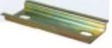 |
TH35-7.5 | ||
| TH35-15 | ||||
| Partition | ||||
| Used for terminating terminal blocks to achieve electrical isolation. |  |
16G | ||
| Test Attachment | ||||
| Test Plug: Used in conjunction with the corresponding component for circuit testing. | ||||
| Quick-Connect Coupler | ||||
| It can be inserted directly into the center of the terminal to establish a connection between terminals. | 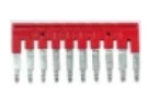 |
2 Bit | FBS 2-12 | |
| 3 Bit | ||||
| 4 Bit | ||||
| 5 Bit | ||||
| 10 Bit | ||||
| 20 Bit | ||||
| 30 Bit | ||||
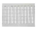
| Marker Strip | ||||
| The marking strips feature standard horizontal and vertical numbering from 1 to 600; alternatively, numbering can be applied based on technical specifications provided by the customer. | blank |  |
middle | ZB 10 (blank) |
| Horizontal Typing | 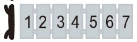 |
ZB 10 (horizontal) | ||
| Vertical Typing | 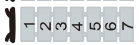 |
ZB 10 (vertical) | ||
 |
Both sides | BFM 8 (blank) | ||
| BFM 8 (horizontal) | ||||
| BFM 8 (vertical) | ||||
| End | ||||
| Tubular Pre-insulated Terminal | 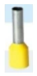 |
E16-18 | ||
| Tubular Non-Insulated Terminal |  |
|||