Understanding The Safety Mission Of The Protective Neutral (pe) Terminal Through The Fault Current Loop
- Type:
- Protective conductor terminal block
- Number Of Connections:
- 2
- Connection Method:
- PowerTurn connection
- Rated Cross Section:
- 35 mm²
- Mounting type:
- DIN Rail (EN 60715)
- Compatible Rail:
- NS 35/7,5, NS 35/15
- Cross Section:
- 2.5 mm² - 35 mm²
- Color:
- green-yellow
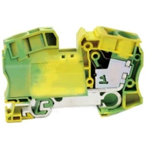
A loose PEN terminal breaks the low-impedance return path. Fault current cannot reach the level needed to trip the breaker, so exposed metalwork stays live. Re-torque to specification, verify rail continuity, and confirm the short-time withstand rating against the prospective fault current at that point.
What a PEN Terminal Does Under Fault
A PEN conductor returns load current during normal operation and carries full fault current during a fault. A rail-bonded earth connector block differs from a standard feed-through terminal because it must not open under fault current. A generic feed-through block may melt, arc, or disconnect under the same stress, removing the return path the protection scheme depends on.
The Failure Sequence: From Loose Screw to Fire
-
Clamping force drops. Vibration or thermal cycling reduces preload on the screw.
-
Contact resistance rises. Oxide layers form at the joint; local temperature climbs.
-
Thermal runaway. Rising resistance raises temperature, which raises resistance further.
-
Insulation degrades. Heat conducts along the cable and scorches the housing.
A published study on a 16mm earth block found higher-rated models carbonised faster as loosening angle increased. Heat conducted along the conductor degrades insulation beyond the terminal itself.
Why the Breaker Does Not Trip
Fault loop impedance (Zs) governs whether the protective device operates within the required time. When Zs rises, fault current falls, and the breaker takes longer to trip or never trips at all. An RCD does not compensate: it relies on a complete PE path that a loose PEN terminal has already interrupted.
Inspection: What to Check On Site
-
Torque verification — re-tighten to the manufacturer's specified value.
-
Rail continuity — measure resistance from the terminal to the rail.
-
Thermal scan — use infrared imaging to locate abnormal hot spots.
-
Conductor preparation — confirm strip length and crimp quality.
A DIN rail is not automatically protective earth. Painted surfaces, isolated rail sections, or corroded joints interrupt the expected path, so continuity should be re-verified after any panel modification.
If Loosening Is Already Found: Repair Steps
Isolate and lock off the circuit before touching the terminal. Replace the block if the housing is scorched or the clamping unit shows deformation; re-torque only if the metal is intact. Where the conductor has been upgraded, an earth terminal block 25mm may be required to keep the protective path rated for the new fault level.
Rating Check: Matching Terminal to Fault Current
| Conductor Size | Rated Current | Short-Time Withstand | Rail Type |
|---|---|---|---|
| 16 mm² | 76–101 A | 2.7 kA | TH35 |
| 25 mm² | 125 A | 4.0 kA | TH35 |
| 35 mm² | 150 A | 6.0 kA | TH35 |
Specifications per manufacturer product literature, model JHD1-35JD, accessed 2026.
A block rated at 80 A continuous may appear adequate for a 63 A circuit. The relevant check is whether it carries the prospective fault current until the breaker trips. Where the available fault current reaches 6 kA, a terminal rated at 2.7 kA short-time withstand becomes the weakest link in the chain.
FAQ
Q: Can a loose PEN terminal cause electric shock?
A: Yes. The broken return path raises exposed metalwork toward line voltage. Contact during this condition can be lethal.
Q: How is an overheating earth terminal detected?
A: Infrared scanning under load, plus periodic torque checks, reveals hot spots before visible damage appears.
Q: Does a loose terminal block affect RCD operation?
A: Yes. RCDs require a complete PE path. A loose terminal block earth connection can prevent the device from sensing fault current.
Q: What torque should a PEN terminal be tightened to?
A: Follow the manufacturer's specification. Insufficient torque is a leading cause of terminal overheating and eventual failure.
| Wiring Diagram |  |
|||
| Thickness/ Height / Width (mm) | 16.2/58.6/92 | |||
| Technical Parameters | ||||
| Rated Data | Voltage (V) | / | ||
| Current (A) | / | |||
| Cross-section (mm²) | 35 | |||
| Crimping Range | Rigid Wire (mm²) | 6-35 | ||
| Flexible Wire (mm²) | 6-35 | |||
| Insulating Material | PA | |||
| Flame retardant rating UL-94 | V0 | |||
| Stripping Length (mm) | 24 | |||
| Install the Guide Rails | TH35-7.5/TH35-15 | |||
| model | ||||
| Partition plate | Integrated cover plate, no partition needed | |||
| Plug-in Bridge | 2P | FBS 2-16 | 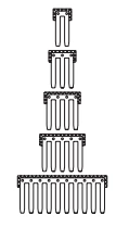 |
|
| Marker Strip | blank | ZB10 | 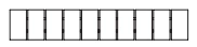 |
|
| Horizontal Printing | ZB10 | 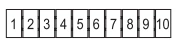 |
||
| Vertical Printing | ZB10 | 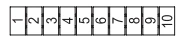 |
||
| Dimensions | 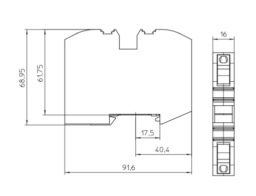 |
|||