PE Line ≠ PEN Line: The Most Common Conceptual Pitfall in Selecting Grounding Terminals
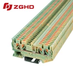
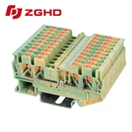
A PE conductor carries fault current only. A PEN conductor combines protective earth and neutral functions, carrying normal neutral current. Confusing the two leads to incorrect grounding terminal blocks selection. A PEN conductor must never be terminated in a PE-only grounding terminal block. This guide explains the difference and selection rules.
PE vs PEN Conductor: What Is the Difference?
A PE conductor connects exposed metal parts to earth and carries no current during normal operation. A PEN conductor returns neutral current and provides fault protection at the same time. IEC 60364-5-54 sets minimum sizes for PEN conductors.
| Feature | PE Conductor | PEN Conductor |
|---|---|---|
| Normal current | None | Full neutral current |
| Min copper size | Per fault loop | 10 mm² |
| Min aluminum size | Per fault loop | 16 mm² |
| Switching allowed | Yes, with lockout | Never |
| Exposed parts in TN-C | Yes | Yes |
In TN-C systems, the PEN conductor may connect exposed conductive parts. After the separation point in TN-C-S, PE and N must remain independent. A PEN conductor cannot be switched or disconnected.
TN System Impact on Terminal Selection
The system type determines whether an earthing connector block can serve the application. TN-C uses a combined PEN path. TN-S uses separate PE and N. TN-C-S splits the PEN at one point.
-
Identify the system type at the distribution point.
-
Trace each conductor to its origin.
-
Confirm whether the PEN conductor is before or after the separation point.
-
Check the terminal rating against continuous neutral current.
Common Confusion Sources
Three situations cause mistakes with a ground junction block. Retrofit projects mix old TN-C wiring with new TN-S circuits. Green/yellow marking alone does not confirm PE status. Space pressure leads to using one conductor for both functions.
-
Green/yellow marking without a PEN label.
-
Legacy TN-C circuits connected to PE busbars.
-
Undersized terminals used for continuous neutral current.
Consequences of Wrong Selection
A ground wire terminal block rated for PE duty may lack continuous current capacity. A PEN conductor in a PE-only terminal overheats. The protective path can break, creating touch voltage risk. Compliance with IEC 60947-7-2 fails.
Selection Steps for Grounding Terminal Blocks
-
Confirm conductor function.
-
Check the system type.
-
Measure the cross-section.
-
Verify continuous current rating for PEN.
-
Check certification for the terminal block earth wire.
-
Confirm PEN conductors cannot be switched.
Parameter Check Example
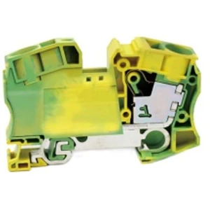
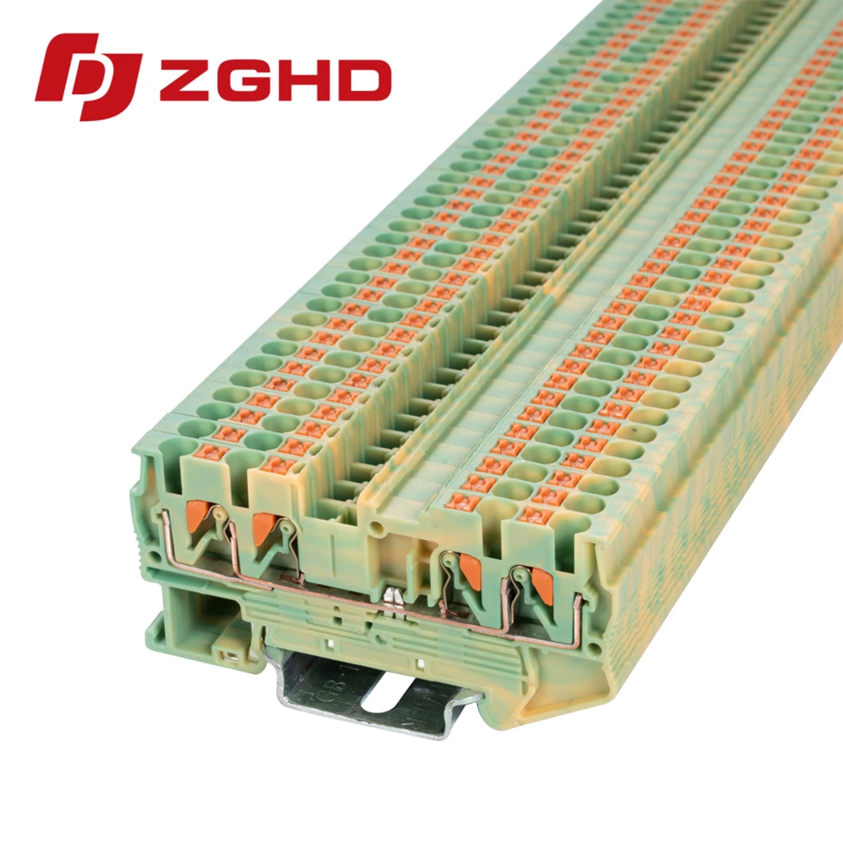
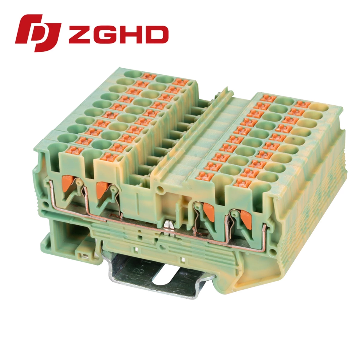
A 2.5 mm² protective conductor terminal block with push-in connection, rigid wire range 0.2 to 4 mm², PA66 housing, and UL-94 V0 rating suits PE applications. That terminal block for earth wire cannot serve as a PEN terminal because the minimum PEN copper size is 10 mm².
Frequently Asked Questions
Q: Can a PEN conductor be connected to a PE terminal block?
A: No. A PEN conductor carries neutral current. A PE-only terminal cannot handle that continuous load.
Q: Is a green/yellow conductor always PE?
A: No. A PEN conductor also uses green/yellow marking but must display the label “PEN.”
Q: Where is PEN separated in TN-C-S?
A: At the main distribution point. After separation, PE and N remain independent.
| Wiring Diagram | 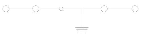 |
| Thickness/Witdh/Height | 5.2*72.4*35.5 mm |
| Nominal cross section | 2.5 mm² |
| Rated current | / |
| Rated voltage | / |
| Color | green-yellow |
| Insulating material | PA66 |
| Flame retardant rating UL-94 | V0 |
| Connection type | Push-in connection |
| The minimum cross section(Rigid wire) | 0.2 mm2 |
| The maximum cross section(Rigid wire) | 4 mm2 |
| The minimum cross section(Soft wire) | 0.2 mm2 |
| The maximum cross section(Soft wire) | 2.5 mm2 |
| Cover | JHD1-2.5/2X2G |
| Jumper | FSB 10-5 |
| Marker | ZB5M |
| Dimensions | 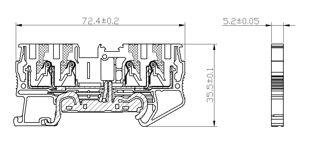 |