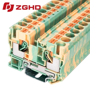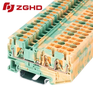
Industrial DIN Rail Earth Grounding Terminal Blocks Wire
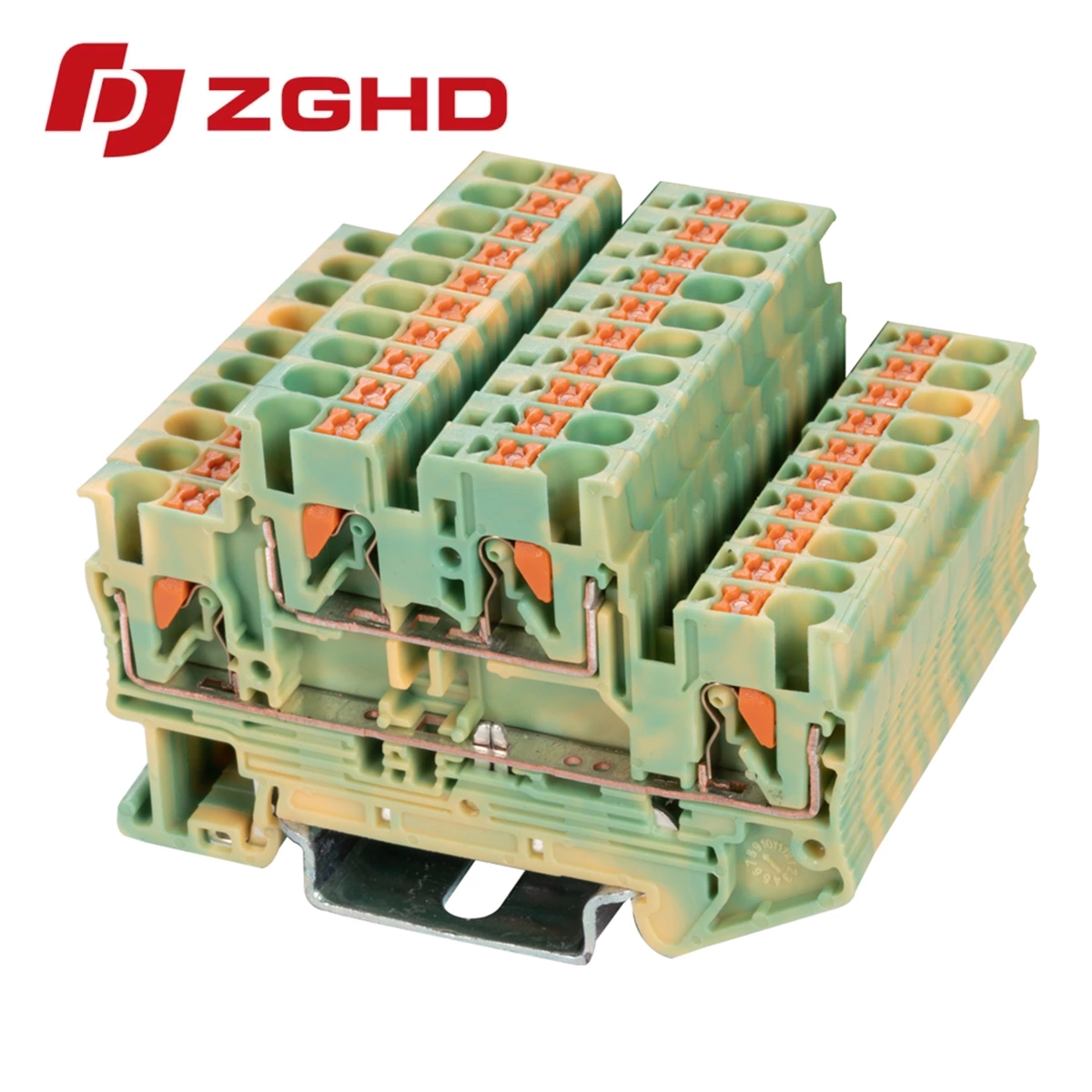
Direct Fault Current Protection for Enclosures
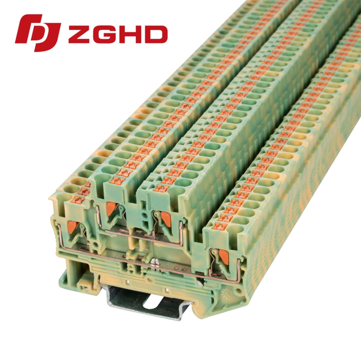
Uninterrupted cabinet safety requires dependable equipotential bonding. High-grade Grounding Terminal Blocks route fault currents away from sensitive automation electronics straight to the cabinet chassis. Installing a dedicated din rail earth block prevents stray voltage accumulation, isolates electrical noise, and protects personnel during short-circuit events.
Technical Specifications
Standardized components maintain compliance across industrial panel assemblies:
| Parameter | Specification |
|---|---|
| Rated Wire Range | 0.2 mm² – 2.5 mm² (24–12 AWG) |
| Standard Compliance | IEC 60947-7-2 |
| Housing Material | PA66 (UL94 V-0 flame rating) |
| Mounting Profile | NS 35/7.5 and NS 35/15 |
| Clamping Mechanism | Push-in spring connection |
Installation and Performance Standards
Cabinet wiring integrity demands components tested for harsh operating conditions. Implementing a standard din earth terminal ensures consistent low contact resistance even under continuous thermal cycling.
Operational Checklist
-
Strip conductors accurately: Expose 10 mm of bare wire without nicking conductor strands.
-
Snap onto carrier rail: Secure the metal foot directly to unpainted steel to guarantee electrical continuity.
-
Inspect clamping retention: Push-in spring cages withstand heavy vibrations without periodic retightening.
Preventing Ground Loops and Electrical Noise
Mechanical vibration often loosens traditional screw clamps over operational cycles. Utilizing a tensioned din rail ground structure eliminates connection failure points across machinery installations.
-
Corrosion resistance: Tin-plated copper alloy busbars resist oxidation in high-humidity enclosures.
-
Visual identification: International green-yellow housing prevents wiring errors during maintenance.
-
Surge management: High short-circuit withstand capacity safely conducts transient overvoltages.
A rugged din rail ground block provides the baseline defense against ground loops and unexpected machinery downtime.
| Wiring Diagram |  |
| Thickness/Witdh/Height | 5.2*68.5*46 mm |
| Nominal cross section | 2.5 mm² |
| Rated current | / |
| Rated voltage | / |
| Color | green-yellow |
| Insulating material | PA66 |
| Flame retardant rating UL-94 | V0 |
| Connection type | Push-in connection |
| The minimum cross section(Rigid wire) | 0.2 mm² |
| The maximum cross section(Rigid wire) | 4 mm² |
| The minimum cross section(Soft wire) | 0.2 mm² |
| The maximum cross section(Soft wire) | 2.5 mm² |
| Cover | JHD1-2.5/2-2G |
| Jumper | FSB 10-5 |
| Marker | ZB5M |
| Dimensions | 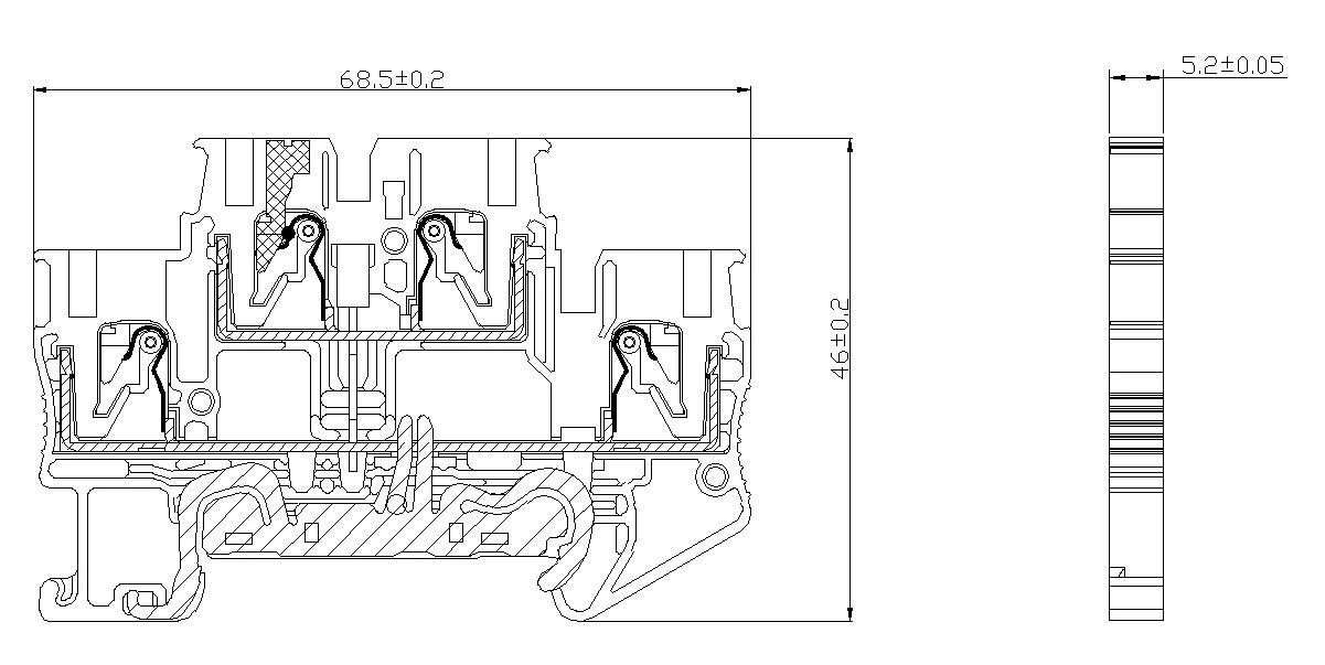 |