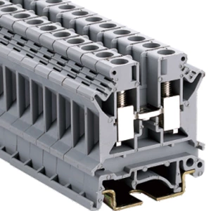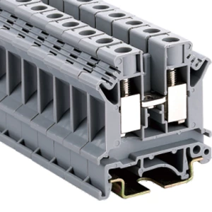
Din Rail Vs Panel Mount: Feed-through Terminal Block Selection
- Type:
- Feed-through terminal block
- Nominal Voltage:
- 690 V
- Nominal Current:
- 32 A
- Number Of Connections:
- 4
- Number Of Positions:
- 1
- Connection Method:
- Screw connection
- Rated Cross Section:
- 4 mm²
- Cross Section:
- 0.2 mm² - 6 mm²
- Color:
- gray
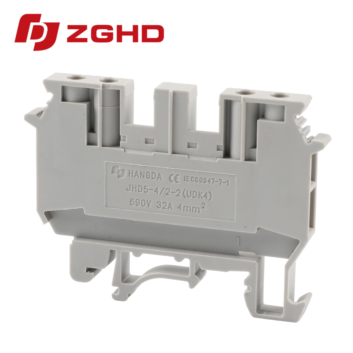
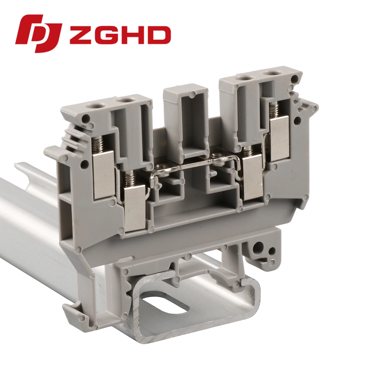
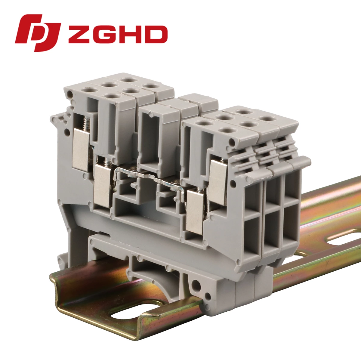
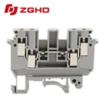
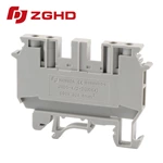
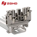
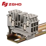
Choose DIN rail when high density and fast service matter. Choose panel mount when vibration and enclosure depth dominate. A feed-through terminal block connects two conductors in one circuit path. This guide compares mounting styles, clamping technologies, and four selection mistakes. It also provides a quick spec table and a final selection sequence.
Quick Specs Before Comparing Mounting Styles
Electrical Ratings
Before evaluating mounting, confirm the circuit's electrical parameters. A feed through terminal block rated at 41 A per UL and 600 V accepts 22–10 AWG conductors with 0.4 Nm torque. Higher-range models reach 62 A per UL and 76 A per IEC with an 18–6 AWG wire range. These figures establish the electrical baseline before mechanical choices.
| Parameter | Typical Range | Checkpoint |
|---|---|---|
| Rated current | 20 A – 76 A | Use 150% of continuous current |
| Rated voltage | 300 V – 1000 V | Match UL or IEC approval |
| Wire range | 24 AWG – 4/0 AWG | UL and IEC may differ |
| Pitch | 5.2 mm – 12 mm | Smaller pitch raises density |
| Torque | 0.4 Nm – 2.0 Nm | Confirm with manufacturer |
Conductor and Environment Checks
-
Confirm solid, stranded, or ferruled conductor.
-
Check ambient temperature and flame rating.
-
Verify vibration exposure before choosing mounting style.
DIN Rail or Panel Mount? Side-by-Side Decision
| Factor | DIN Rail | Panel Mount |
|---|---|---|
| Installation speed | Fast snap-on | Slower bolt-on |
| Enclosure depth | Needs more depth | Lower profile |
| Vibration | Moderate | High resistance |
| Heat dissipation | Better airflow | Depends on housing |
| Maintenance | Easy module swap | Harder access |
| Typical use | Control cabinets | Compact or mobile equipment |
When DIN Rail Wins
DIN rail-mounted feed through terminals snap onto a standard 35 mm rail. Installation is fast, and modules can be added or replaced without rewiring adjacent positions. The open architecture provides better heat dissipation in high-power applications. Frequent circuit changes favor this mounting style. Rail depth must be confirmed during enclosure design.
When Panel Mount Wins
Panel-mounted feed through terminals bolt directly to an equipment housing or backplate. This configuration offers superior mechanical stability in high-vibration settings and saves enclosure space. The trade-off is installation labor. Panel mounting requires drilling, hardware alignment, and fastener work compared to snapping onto a rail. Compact enclosures often justify this labor cost.
Decision Rule
-
If circuits change often → DIN rail.
-
If vibration is constant → panel mount.
-
If cabinet depth is tight → panel mount.
-
If high heat load → DIN rail.
Screw, Spring, or Push-In Clamping
| Feature | Screw Clamp | Spring Cage | Push-In |
|---|---|---|---|
| Tool needed | Yes | Yes | No for solid wire |
| Vibration resistance | Moderate | High | High |
| Wiring speed | Slow | Medium | Fast |
| Large conductor | Yes | Limited | Limited |
| Re-torque | Required | Not required | Not required |
Screw Clamp
Screw terminals apply clamp force through a tightened screw. They handle the largest conductor sizes, exceed 6 mm², and allow visible re-torque during maintenance. The drawback is labor: each connection demands individual torque application. Loose screws remain a leading cause of terminal failure when maintenance schedules are ignored.
Spring Cage
Spring cage feed through modular terminal block holds constant clamping pressure without a screw. A tool opens the cage before wire insertion, but the connection resists vibration without re-torquing. Spring cage designs suit moderate conductor sizes and applications where maintenance access is limited. They also tolerate thermal cycling.
Push-In
Push-in technology permits direct wire insertion into a spring-loaded contact. Solid wire enters without a tool; stranded wire requires a ferrule. Wiring time drops by approximately 50% compared to screw terminals. Pull-out force exceeds that of screw or spring-cage connections. Above 6 mm², screw clamp remains preferred. Push-in feed through terminals suit low-maintenance installations.
Four Selection Mistakes
-
Skipping the 150% current rule. Specifying a terminal at the exact continuous current leads to thermal degradation. Choose a rating at least 1.5 times the expected peak.
-
Ignoring conductor preparation. Stranded wire without a ferrule frays inside the clamp, creating a loose connection that resists diagnosis.
-
Confusing circuit function. A feed-through block performs wire-to-wire connection. Protective earth, fused, and disconnect terminals have different circuit roles and cannot be substituted.
-
Overlooking multi-level options. When cabinet space is constrained, multi conductor terminal blocks and multi level terminal blocks provide the same circuit count within a smaller footprint.
FAQ
Q: What is the difference between DIN rail and panel mount feed-through terminal blocks?
A: DIN rail snaps onto a 35 mm rail. Panel mount bolts to a housing. DIN rail suits serviceability. Panel mount suits vibration and compact depth. Both accept the same conductor ranges when ratings match.
Q: Can push-in terminals accept stranded wire?
A: Yes, with a ferrule. Without a ferrule, stranded wire may fray and reduce contact quality. Solid wire needs no tool.
Q: How to choose between multi conductor and multi level terminal blocks?
A: Use multi conductor terminal blocks when several conductors share one potential. Use multi level terminal blocks when vertical space is limited and circuits must stay separated. Check voltage ratings between levels.
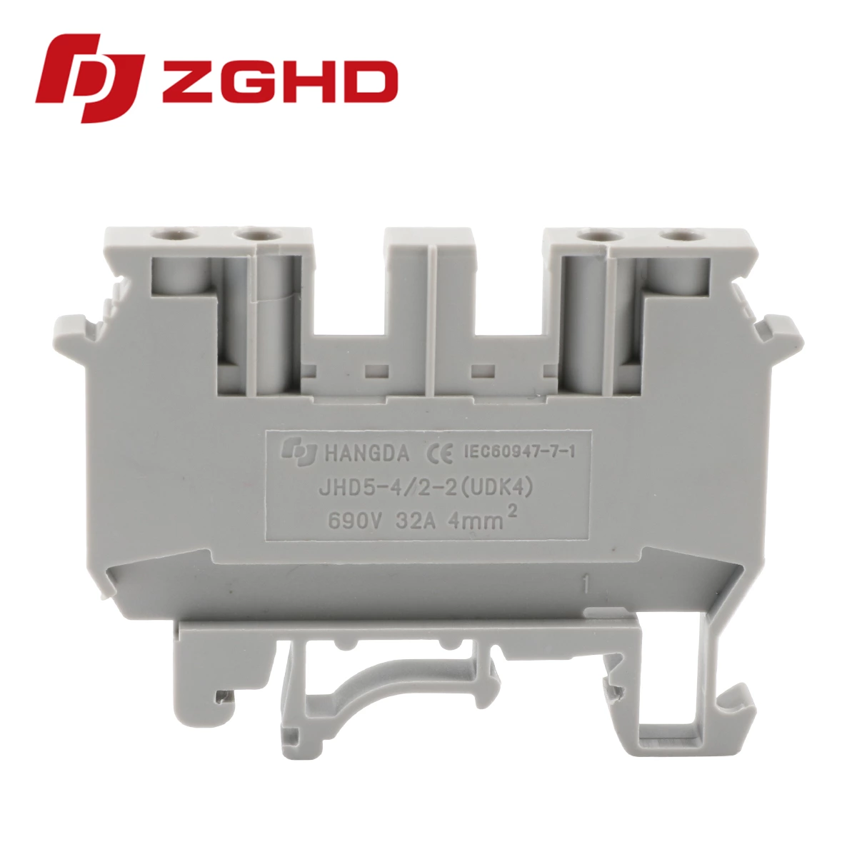
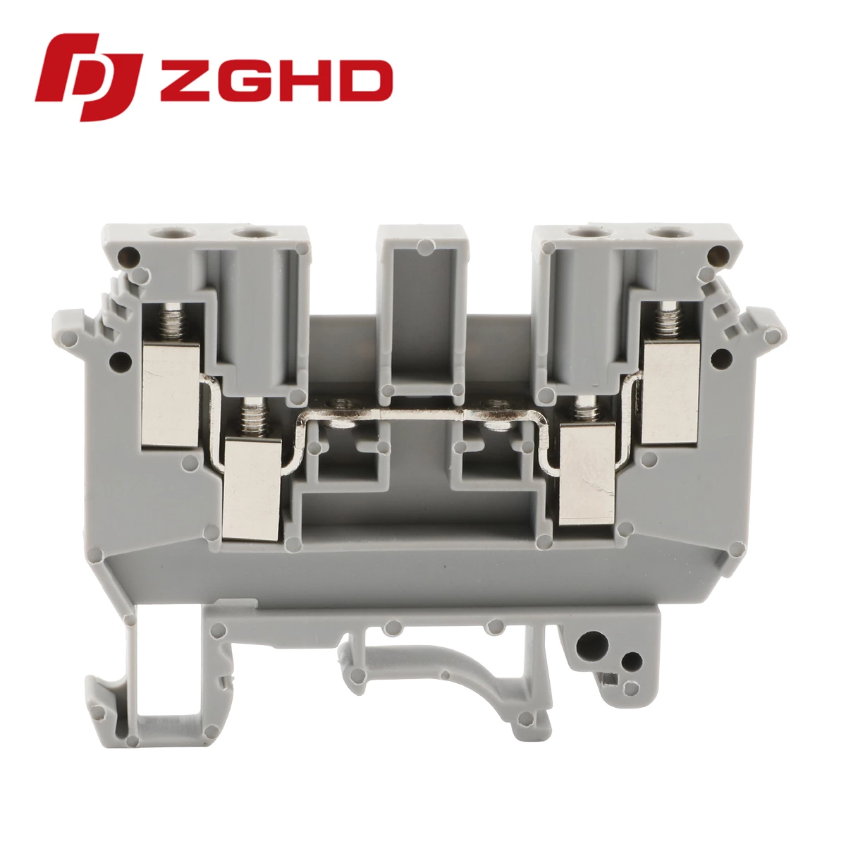
| Model | Function | Wire IEC cross-section | Wire UL | Thickness | Maximum current | Number of packages | Thickness/Height( )/Width mm )/Width mm |
Rated voltage/rated current/rated cross-sectior |
| JHD5-4/2-2 | 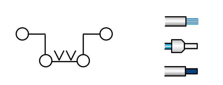 |
4 mm² 2.5 mm² 4 mm² | 12 AWG 14 AWG 12 AWG | 6.2 mm | 32 A | 70 | 6.2/47/63.5 | 690 V/32 A/4 mm² |
Specfication:
| End cover | D-4/2-2 |
| Cross-connection 10-Polo,Separable | ZL2-4 ZL3-4 ZL10-4 |
| Insertion bridge 10-Polo,Separable | BLS2-4 BLS3-4 BLS10-4 |
| Small Partition | CPK3 |
| Marking tags | ZB6 |
| Screw/Tightening torque(Nm) | M3/0.6 |
| Material | PA |
| Flame retardant rating UL-94 | V0 |
| Dimensions | 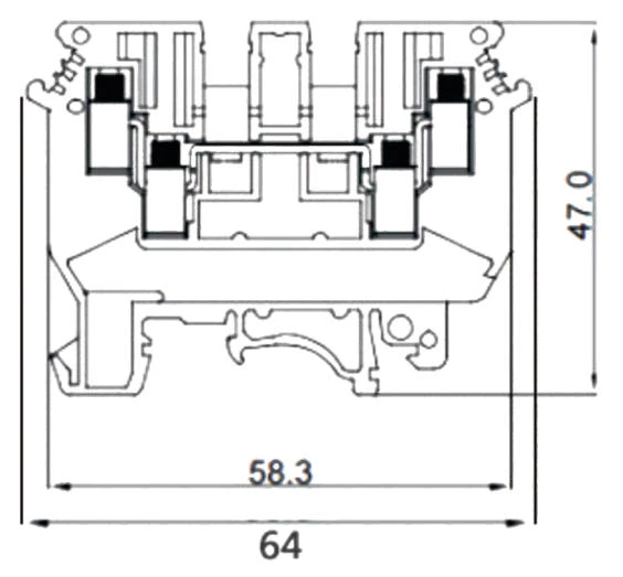 |
With universal mounting feet for standard top-hat(Ω profile) and G-profile DIN rail mounting.