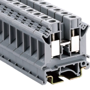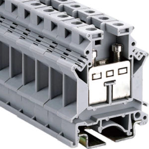
Why Screw Type Terminal Blocks Are Called The “most Standard” Wiring Method
- Type:
- Feed-through terminal block
- Nominal Voltage:
- 800 V
- Nominal Current:
- 41 A
- Number Of Connections:
- 2
- Connection Method:
- Screw connection
- Rated Cross Section:
- 6 mm²
- Cross Section:
- 0.2 mm² - 10 mm²
- Color:
- gray
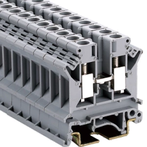
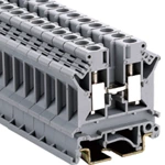
Screw type terminal blocks are the default wiring method because they need only a standard screwdriver, allow torque verification, and cost $0.27–$0.58 per unit at volume. A din rail screw terminal block accepts 0.2–6 mm² conductors (24–8 AWG) and supports two wires per point. This article covers why they became standard, when they fail, and how to select one.
Three Conditions That Make a Wiring Method Standard
-
Standard tools. No proprietary release mechanism is required.
-
Torque verification. A gas-tight connection can be measured and recorded.
-
Cost predictability. Unit price stays stable from prototype to production.
The JHD5-6 feed-through terminal block meets all three. It takes 0.2–6 mm² wire and tightens to 0.7–0.8 Nm.
Screw vs Spring Clamp: What Changes at the Terminal
| Feature | Screw | Spring | Push-in |
|---|---|---|---|
| Torque check | Yes | No | No |
| Tool needed | Screwdriver | Release tool | Release tool |
| Conductors per point | Two | One | One |
| Rewire reuse | Full | Spring fatigue | Limited |
| Vibration resistance | Torque-dependent | Constant force | Constant force |
A clamp terminal block saves installation time but removes torque measurement from the record. For high-current circuits, that record separates a routine install from a documented one.
Where Screw Type Terminal Blocks Still Win
Temperature measurement circuits
A thermocouple screw terminal presses the TC+/TC− leads directly into the conductor. Every extra junction adds a potential error source. A plug-and-receptacle connection adds one. The screw terminal does not.
Vibration and thermal cycling
Torqued to specification, screw terminals form gas-tight connections that resist loosening across wide temperature ranges.
Distribution and jumper work
A din rail screw terminal block secures two conductors under one screw, which suits jumper and distribution work.
When Screw Terminals Are the Wrong Choice
-
High-density, fast-wiring panels where installation speed matters.
-
Strong vibration without a re-torque schedule.
-
Over-torqued conductors that deform the wire.
-
Humid or corrosive sites without plated contacts.
-
Tight spaces where clamp type terminal blocks fit better.
How to Select a Screw Type Terminal Block
-
Confirm rated voltage and current.
-
Confirm conductor cross-section and AWG range.
-
Confirm mounting: rail, panel, or PCB.
-
Confirm materials: PA66, copper alloy, tin or nickel plating.
-
Confirm certification: IEC 60947-7-1, UL 1059, RoHS.
-
Confirm torque value and write it into the work instruction.
| Check | What to Confirm | Example |
|---|---|---|
| Voltage | Rated insulation voltage | 800 V |
| Current | Continuous current | 41 A |
| Conductor | Solid, stranded, ferruled | 0.2–6 mm² |
| Mounting | Rail or panel | 35 mm rail |
| Torque | Screw specification | 0.7–0.8 Nm |
View the JHD5-6 full specifications, download drawings, or request samples.
FAQ
Q: What is a screw type terminal block?
A: A terminal block that secures a conductor when a screw compresses it against a metal body.
Q: Why are screw type terminal blocks called the default wiring method?
A: They need standard tools, allow torque checks, and cost less per unit than alternatives.
Q: Screw terminal vs spring clamp: which is faster?
A: Spring clamp installs faster. Screw terminals allow torque verification, which spring designs cannot.
Q: What torque should be used on a screw terminal block?
A: Follow the manufacturer's rating. The JHD5-6 uses 0.7–0.8 Nm.
Q: When should a thermocouple screw terminal be used?
A: In temperature circuits where extra junctions would add measurement error.
Q: Are screw terminals suitable for high-vibration applications?
A: Yes, when torqued to specification and checked on a maintenance schedule.
| Model | Function | Wire IEC cross-section | Wire UL | Thickness |
| JHD5-6 | 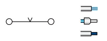 |
6 mm² 4 mm² 6 mm² |
10 AWG 12 AWG 10 AWG |
8.2 mm |
| Maximum current | Number of packages | Thickness/Height( )/Width mm )/Width mm |
Rated voltage/rated current/rated cross-sectior |
| 41 A | 75 | 8.2/47/42.5 | 800 V/41 A/6 mm² |
Specfication:
| End cover | D2.5-10 |
| Cross-connection 10-Polo,Separable | ZL2-6 ZL3-6 ZL10-6 |
| Insertion bridge 10-Polo,Separable | BLS2-6 BLS3-6 BLS10-6 |
| Partition plate | FP |
| Small Partition | CP |
| Marking tags | ZB8 |
| Screw/Tightening torque(Nm) | M4/1.2 |
| Material | PA |
| Flame retardant rating UL-94 | V0 |
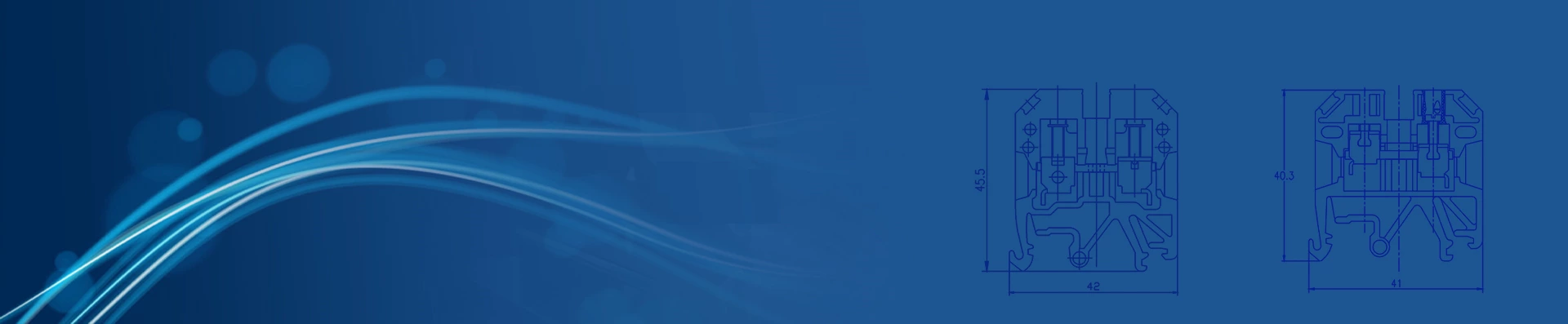
| Dimensions | 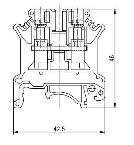 |
With universal mounting feet for standard top-hat(Ω profile) and G-profile DIN rail mounting.