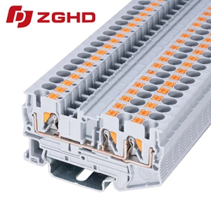
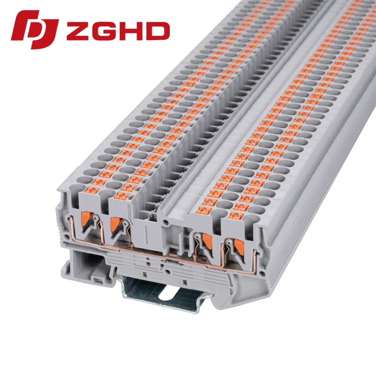
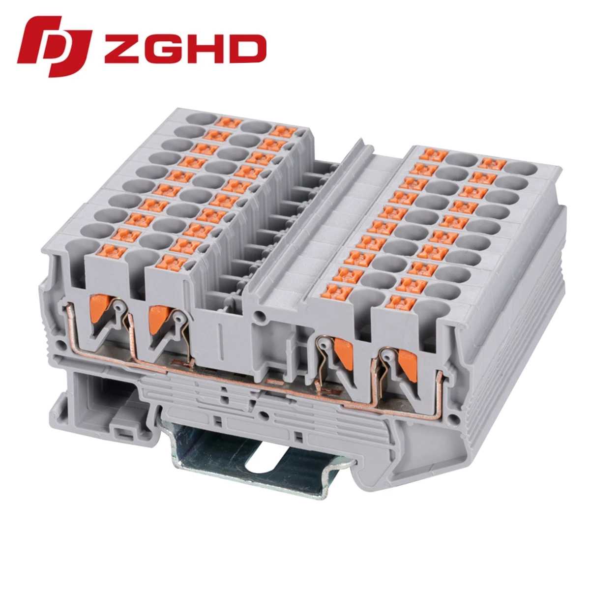
Modular Multi Level Conductor Feed-through Terminal Blocks
- Type:
- Multi-conductor terminal block
- Nominal Voltage:
- 800 V
- Nominal Current:
- 24 A
- Number Of Connections:
- 4
- Connection Method:
- Push-in connection
- Rated Cross Section:
- 2.5 mm²
- Mounting type:
- DIN Rail (EN 60715)
- Compatible Rail:
- NS 35/7,5, NS 35/15
- Cross Section:
- 0.14 mm² - 4 mm²
- Color:
- gray
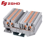
High-density control cabinets require compact wiring architectures without sacrificing signal integrity. Standard DIN rail configurations frequently run out of panel space, making multi conductor terminal blocks an efficient solution for routing multiple termination points inside cramped enclosures.
Optimizing Cabinet Space and Wire Routing
Compact electrical distribution benefits significantly from multi-tier routing architecture. Deploying feed through terminals streamlines panel wireways, separating distinct circuit potentials onto dedicated vertical levels while maintaining low contact resistance across automated industrial equipment.
Cable Management and Potential Distribution
Efficient panel layout relies on versatile connection technology to handle complex signal pathways:
-
Vertical Footprint Reduction: Utilizing standard single-tier blocks and multi level terminal blocks provides substantial space savings along mounting rails.
-
Vibration-Proof Retention: Screw-clamp assemblies maintain gas-tight conductor clamping under continuous mechanical oscillation.
-
Cross-Connection Flexibility: Plug-in jumper bars enable fast voltage bridging between adjacent feed through terminal blocks without extra wiring.
Technical Specifications
| Parameter | Value |
|---|---|
| Rated Voltage | 800 V |
| Rated Current | 24 A |
| Conductor Cross-Section | 0.2 - 2.5 mm² (24 - 14 AWG) |
| Housing Material | Polyamide PA66 |
| Flammability Rating | UL 94 V-0 |
| Mounting Type | DIN Rail 35 mm |
Selection Guidelines for Industrial Control Panels
Choosing an appropriate feed through modular terminal block requires matching conductor cross-sections with cabinet thermal dissipation limits. Polyamide PA66 housing prevents surface tracking, while high impulse withstand ratings safeguard connected automation interfaces against destructive transient overvoltages.
Pre-Commissioning Inspection Checklist
-
Ensure stripped conductor length matches internal clamp depth to prevent exposed copper.
-
Apply calibrated torque values onto terminal clamping screws.
-
Secure insulated end covers onto open terminal sides prior to energization.
| Wiring Diagram | 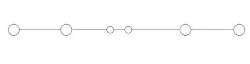 |
| Thickness/Witdh/Height | 5.2*72.4*35.5 mm |
| Nominal cross section | 2.5 mm² |
| Rated current | 24 A |
| Rated voltage | 500 V |
| Color | Gray |
| Insulating material | PA66 |
| Flame retardant rating UL-94 | V0 |
| Connection type | Push-in connection |
| The minimum cross section(Rigid wire) | 0.2 mm² |
| The maximum cross section(Rigid wire) | 4 mm² |
| The minimum cross section(Soft wire) | 0.2 mm² |
| The maximum cross section(Soft wire) | 2.5 mm² |
| Cover | JHD1-2.5/2-2G |
| Jumper | FSB 10-5 |
| Marker | ZB5M |
| Dimensions | 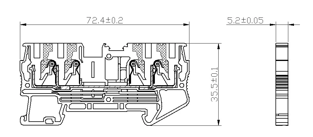 |