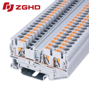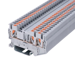
Push In And Fit DIN Rail Type Terminal Block Connectors
- Type:
- Multi-conductor terminal block
- Nominal Voltage:
- 500 V
- Nominal Current:
- 17.5 A
- Number Of Connections:
- 4
- Connection Method:
- Push-in connection
- Rated Cross Section:
- 1.5 mm²
- Mounting type:
- DIN Rail (EN 60715)
- Compatible Rail:
- NS 35/7,5, NS 35/15
- Cross Section:
- 0.14 mm² - 1.5 mm²
- Color:
- gray


Streamlining Cabinet Wiring with Direct Insertion
Wiring industrial control cabinets requires components that reduce assembly hours while preventing loose connections. Modern Push-In Type Terminal Blocks replace traditional screw clamps with pre-stressed stainless steel springs. Inserting solid conductors or stranded wires with ferrules directly into the push in terminal block achieves tool-free installation, cutting wiring duration over fifty percent compared to threaded terminals.
Operational Advantages on Standard Mounting Rails
Mechanical Stability Under Industrial Conditions
Severe machine vibration causes screw terminals to loosen, resulting in unexpected downtime. Deploying push fit din rail terminals eliminates routine retightening through constant spring contact pressure.
-
Continuous contact force maintains gas-tight connections under severe mechanical shock.
-
Flame-retardant PA66 housings provide UL94 V-0 protection inside dense distribution cabinets.
Rapid Assembly and Maintenance Workflows
Each push fit terminal block features an integrated orange release button and dedicated test tap points.
-
Tool-free front connection allows rapid wire entry even inside restricted ducting spaces.
-
Standardized push-in jumpers enable fast potential distribution across adjacent channels.
Technical Specifications
| Parameter | Standard Value |
|---|---|
| Cross Section | 0.14 mm² – 1.5 mm² |
| Rated Voltage / Current | 500 V / 17.5 A |
| Stripping Length | 8 mm – 10 mm |
| Mounting Standard | NS 35 DIN Rail |
| Flammability Rating | UL 94 V-0 |
High-Density Panel Integration
Multi-conductor feed-through architecture maximizes rail space inside compact enclosures. A 1.5 mm² push in type terminal block allows dual-conductor branching on a single level, reducing cabinet footprint while keeping wiring organized. Upgrading existing installations with these components ensures compliant, maintenance-free distribution for automated production lines.
| Wiring Diagram |  |
|||
| Thickness/ Height / Width (mm) | 3.5/30.5/63.4 | |||
| Technical Parameters | ||||
| Rated Data | Voltage (V) | 500 | ||
| Current (A) | 17.5 | |||
| Cross-section (mm²) | 1.5 | |||
| Crimping Range | Rigid Wire (mm²) | / | ||
| Flexible Wire (mm²) | 0.2-1.5 | |||
| Insulating Material | PA | |||
| Flame retardant rating UL-94 | V0 | |||
| Stripping Length (mm) | 11 | |||
| Install the Guide Rails | TH35-7.5/TH35-15 | |||
| model | ||||
| Partition plate | ||||
| Plug-in Bridge | 2P | FBS 2-3.5 | 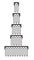 |
|
| 3P | FBS 3-3.5 | |||
| 4P | FBS 4-3.5 | |||
| 5P | FBS 5-3.5 | |||
| 10P | FBS 10-3.5 | |||
| Marker Strip | blank | ZB3.5 | 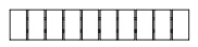 |
|
| Horizontal Printing | ZB3.5 | 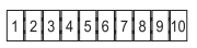 |
||
| Vertical Printing | ZB3.5 | 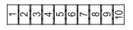 |
||
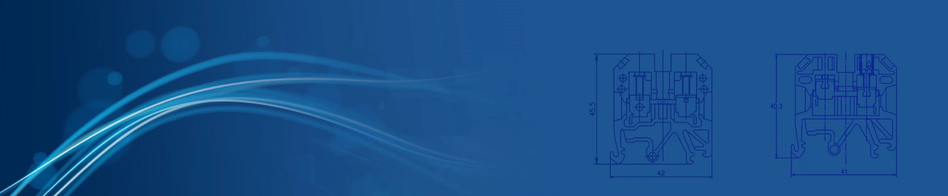
| Dimensions |  |
|||